| Oshkosh MB-5 | |
|---|---|
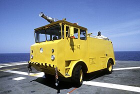
 An Oshkosh MB-5 on board the amphibious assault ship USS Nassau. An Oshkosh MB-5 on board the amphibious assault ship USS Nassau. | |
| Overview | |
| Type | Fire Engine |
| Manufacturer | Oshkosh Truck Corp. |
| Production | 1968-1971 (unconfirmed) |
| Assembly | United States; Oshkosh, Wisconsin |
| Body and chassis | |
| Class | Class 6; Medium Duty truck |
| Layout | Longitudinal, Rear-engine, Four-wheel drive |
| Doors | 2 |
| Powertrain | |
| Engine | 638 cu in (10.7 L) Caterpillar 1673 I6 Diesel Turbocharged |
| Capacity | 660 ft/lbs at 1600 rpm |
| Power output | 273 hp at 2200 rpm |
| Transmission | 4-speed Twin-Disk TD-41-1112 semi-automatic |
| Dimensions | |
| Wheelbase | 140.0 in |
| Length | 252.0 in |
| Width | 96.0 in |
| Height | 132.0 in |
| Curb weight | 22000 lbs |
| Chronology | |
| Predecessor | American LaFrance MB-5 |
| Successor | Oshkosh P-4 |
The Oshkosh MB-5 is a specialized aircraft rescue and firefighting (ARFF) vehicle built by Oshkosh Corporation (formerly Oshkosh Truck Corp.) for putting out fires on-board aircraft carriers. It was designed for rapid deployment of multiple firefighting media by a crew of 4, with a relatively compact design. However, What set this truck apart from other ARFF vehicles of the time was its ability to pump water while moving. This feature, along with its powerful 10.7 L Caterpillar diesel engine and four-wheel drive, made the MB-5 a staple of US military firefighting. It could be seen on US aircraft carriers and airbases both during and after the Vietnam War, continuing service for almost a decade after production of the truck stopped in late 1971 (unconfirmed).
History
The MB-5 was originally built by American LaFrance., starting in the early 1950s. This version of the truck (referred to in military manuals as the "Old model") had a few features that set it apart from the Oshkosh version. For one, many of these trucks had a static spotlight mounted directly above the cab, plus a flatter design with sliding doors as opposed to hinged doors that were present on the Oshkosh version. When the contract for American LaFrance's MB-5 ended, the navy selected Oshkosh Corporation to be the next designer. Design constraints stipulated that the vehicle was to function on aircraft carriers and shore stations, while also being similar in operation to its predecessor. The truck Oshkosh presented was unlike any other on the market to date, being the first fire truck equipped with pump and roll capabilities. Although the MB-5 was designed for use on aircraft carriers, it had many features that made it an ideal fire truck for shore-based airports. It was quickly shipped all over the country, and the MB-5 became the most common fire truck in military airbases. They lasted for years, even receiving modifications until their retirement. Their removal from the military in the early 1980s was not the end of their life, however. Many civilian airports began buying them as surplus with some using the MB-5 until the early 1990s.
Firefighting Equipment
The Oshkosh MB-5 featured a variety of firefighting media. These included a foam turret, a handline, a dry-chemical system, and extinguisher storage. Additionally, the truck featured a second diesel engine made for powering hand tools and other equipment.

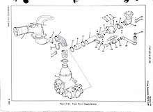
The roof-mounted turret was designed by Cardox Ltd and fed by a 14 pounds per square inch (97 kPa) rotary vein pump (also built by Cardox Ltd). It was manned by one firefighter, who would stand in a roof hatch. This hatch was positioned to the rear of the cab and would latch shut. To open the hatch the operator would simply pull back on the latch holding it in place, and then push up. The turret was of multi-piece construction, with a water deflecting component attached to the end of the nozzle. This, combined with the adjusting handle, allowed the turret to have an infinitely variable spray pattern. Below the turret was a 90° pipe angle, connected to a 4+1⁄2 inches (110 mm) diameter hose visible in the cab. This hose was connected directly to the output of the turret pump. The turret had a wide range of motion, capable of pitching 25° while aiming down, and 60° aiming up. It could also yaw 360° in both directions, but this range was limited by the operator's reach. To the right of the turret was a selection lever, which would allow the turret to output foam or water depending on the turret operator's selection.

The handline was designed by Ardmore Mfg Co and was fed by a 150 pounds per square inch (1,000 kPa) centrifugal pump (built by Waterous Pump Co). The hose reel was mounted at the front of the cab, just underneath the front bumper. While in motion, it would be covered by a hatch that stayed closed using a simple latch. The hose itself was 100 feet (30 m) long, and 1 inch (25 mm) in diameter. Once pulled out, it could be rewound using the electronic rewinding motor activated with a white button to the left of the hose. The end could be customized with one of three different attachments, each for a different purpose.
- Water Nozzle - Short, straight nozzle
- Foam Nozzle - 2 inches (50 mm) nozzle that mixed water and AFFF concentrate
- Bayonet Nozzle - Long pole, used to stab an aircraft's skin and apply a mist to the interior
All were equipped with a quick-release adapter and had variable volumes selected by twisting the end of the attachment. When not in use, the attachments were simply placed inside the hatch before it was closed for storage.
The dry chemical system consisted of a hose reel (manufactured by Hannay), a large Purple-K (PKP) canister, and a nitrogen tank. The hose reel was 100 feet long, with a 3/4 inch diameter hose. The end of the hose consisted of a single attachment, which could be opened and closed using a lever/handle mounted to the top. The firefighter operating it would pull back on the handle to release the dry chemical. The dry chemical hose, much like the front handline, had an electric rewind system activated with a button mounted above the reel. The PKP canister was a large, upright tank with two hoses attached to a valve on top of the canister. One hose carried an inflow of pressurized nitrogen, and the other was an output to the 100-foot hose reel. The canister would have been filled with 150 pounds of PKP, loaded through the top. A nitrogen canister charged to 2500 psi would feed this tank through a 60 psi regulator. The compressed air would exit the PKP tank with the powder, and leave the end of the hose in a large white cloud. An alternative to using the dry chemical hose was to grab one of the many handheld fire extinguishers. The MB-5 had multiple mounts for Purple-K extinguishers, with 5 on the top deck, and 3 in a curbside compartment. These could be used to apply dry chemical where the hose didn't reach.
The MB-5 was equipped with a 400-US-gallon (1,500 L) water tank that was used by both the handline, and foam turret. It could be loaded via a hydrant in a curbside compartment by connecting to the hydrant fill valve, or by another miscellaneous water source using the fill hatch mounted on the top of the rear truck deck. It could be emptied using a valve just below the hydrant fill valve on the roadside of the vehicle. the tank was of one-piece construction and made of fiberglass. The inside was separated by 4 baffles to minimize sloshing while underway. The MB-5 was also built with a 30 gallon tank for an AFFF concentrate (Firefighting foam). It could be filled through a deck fill hatch (just like the water tank), or with a provided hand pump that connected to a foam fill valve on the roadside of the vehicle. Both the handline and foam turret also draw from this tank.
The crews of the MB-5 also had a wide variety of miscellaneous tools and equipment at their disposal. Here is a complete list of standard items that would have been found on board:
- 10 feet (3 m) one-piece aluminum ladder - mounted with hooks on the curbside of the truck
- Electric circular saw - powered by 110v outlet built into its storage compartment
- Halligan bar - mounted with spring-loaded hooks to the inside of the cab just behind the passenger seat
- Hydrant wrench - mounted in the forward curbside compartment
- Foldable spanner wrench - mounted in the forward curbside compartment
- 110v single-cylinder diesel generator - mounted forward of the main engine with remote starting in the cab
- 12v two way radio - mounted inside the cab, with an antenna on the roof
Drive Systems

The Oshkosh MB-5 was built with a turbocharged Caterpillar 1673 diesel engine, which outputs to a Twin Disk TD-41-1112 4-speed "Power shift" Semi-automatic transmission. Gears were selected using a simple stick mounted to the right of the driver's seat, and were arranged sequentially. They were labeled in order, using a sticker with R N 1 2 3 4 to represent gears. The selector had notches where the stick would sit, with one between every other selection. This required the operator to rotate the stick out of the selected gear, similar to how a conventional manual transmission requires the driver to move the stick in and out of the desired gear's location. The main difference was that the action of moving the stick out had no mechanical effect on the transmission, as the notches only served to prevent the operator from accidentally over-shifting if they weren't looking at the gear selector. The transmission used a multi-clutch system, with one clutch for every selectable gear. This allowed a selection to be made while the engine still gave power meaning drivers could shift without letting go of the gas.
The truck had the ability to move from a dead stop while in fourth gear, given that it was not towing a load or was maneuvering with the pumps engaged. This was possible because of the automatic shifting mode, which engaged when 4th gear was selected. This worked in tandem with the 8FLW-1452 single-stage torque converter (also made by Twin Disk Inc).
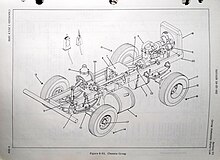
The MB-5 featured 4-wheel drive, with no-slip differentials on the rear axle. The Marine Corps variants of the truck featured no-slip differentials on the front axle assembly as well. The full floating axles sat on leaf spring suspension, mounted to both the front and rear of the frame. While unloaded, the truck's suspension was quite rigid; and there was even a noticeable tilt to the left side which compensated for the extra weight when the water tank was full.

Turning was achieved with a hydraulically boosted mechanical link from the steering column to the forward drive assembly. A similar dual-actuated system also applied the brakes, with an air-over-hydraulic setup. This allowed for a mechanical parking brake within the transmission.
Gallery
References
- ^ Training Program Development Center, Naval Education and (1975). "4". Aviation Boatswain's Mate H 1 & C. United States: Naval Education and Training Support Command. pp. 53–93.
- ^ "Truck, Fire Fighting, Aircraft, Rescue - Type MB-5".
- ^ Technical Manual, Operation, Service, and Repair Instructions With Illustrated Parts Breakdown - Type MB-5 Truck, Firefighting, Aircraft Rescue - NAVAIR 19-25-162. United States: Commander of the Naval Air Systems Command. 1970.


