In signal processing, control theory, electronics, and mathematics, overshoot is the occurrence of a signal or function exceeding its target. Undershoot is the same phenomenon in the opposite direction. It arises especially in the step response of bandlimited systems such as low-pass filters. It is often followed by ringing, and at times conflated with the latter.
Definition
Maximum overshoot is defined in Katsuhiko Ogata's Discrete-time control systems as "the maximum peak value of the response curve measured from the desired response of the system."
Control theory
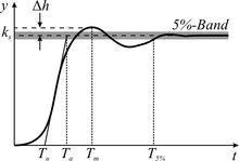
In control theory, overshoot refers to an output exceeding its final, steady-state value. For a step input, the percentage overshoot (PO) is the maximum value minus the step value divided by the step value. In the case of the unit step, the overshoot is just the maximum value of the step response minus one. Also see the definition of overshoot in an electronics context.
For second-order systems, the percentage overshoot is a function of the damping ratio ζ and is given by
The damping ratio can also be found by
Electronics

In electronics, overshoot refers to the transitory values of any parameter that exceeds its final (steady state) value during its transition from one value to another. An important application of the term is to the output signal of an amplifier.
Usage: Overshoot occurs when the transitory values exceed final value. When they are lower than the final value, the phenomenon is called "undershoot".
A circuit is designed to minimize rise time while containing distortion of the signal within acceptable limits.
- Overshoot represents a distortion of the signal.
- In circuit design, the goals of minimizing overshoot and of decreasing circuit rise time can conflict.
- The magnitude of overshoot depends on time through a phenomenon called "damping." See illustration under step response.
- Overshoot often is associated with settling time, how long it takes for the output to reach steady state; see step response.
Also see the definition of overshoot in a control theory context.
Gibbs phenomenon

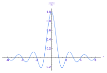
In the approximation of functions, overshoot is one term describing quality of approximation. When a function such as a square wave is represented by a summation of terms, for example, a Fourier series or an expansion in orthogonal polynomials, the approximation of the function by a truncated number of terms in the series can exhibit overshoot, undershoot and ringing. The more terms retained in the series, the less pronounced the departure of the approximation from the function it represents. However, though the period of the oscillations decreases, their amplitude does not; this is known as the Gibbs phenomenon. For the Fourier transform, this can be modeled by approximating a step function by the integral up to a certain frequency, which yields the sine integral. This can be interpreted as convolution with the sinc function; in signal processing terms, this is a low-pass filter.
Signal processing


In signal processing, overshoot is when the output of a filter has a higher maximum value than the input, specifically for the step response, and frequently yields the related phenomenon of ringing artifacts.
This occurs for instance in using the sinc filter as an ideal (brick-wall) low-pass filter. The step response can be interpreted as the convolution with the impulse response, which is a sinc function.
The overshoot and undershoot can be understood in this way: kernels are generally normalized to have integral 1, so they send constant functions to constant functions – otherwise they have gain. The value of a convolution at a point is a linear combination of the input signal, with coefficients (weights) the values of the kernel. If a kernel is non-negative, such as for a Gaussian kernel, then the value of the filtered signal will be a convex combination of the input values (the coefficients (the kernel) integrate to 1, and are non-negative), and will thus fall between the minimum and maximum of the input signal – it will not undershoot or overshoot. If, on the other hand, the kernel assumes negative values, such as the sinc function, then the value of the filtered signal will instead be an affine combination of the input values, and may fall outside of the minimum and maximum of the input signal, resulting in undershoot and overshoot.
Overshoot is often undesirable, particularly if it causes clipping, but is sometimes desirable in image sharpening, due to increasing acutance (perceived sharpness).
Related concepts
A closely related phenomenon is ringing, when, following overshoot, a signal then falls below its steady-state value, and then may bounce back above, taking some time to settle close to its steady-state value; this latter time is called the settle time.
In ecology, overshoot is the analogous concept, where a population exceeds the carrying capacity of a system.
See also
References and notes
- Ogata, Katsuhiko (1987). Discrete-time control systems. Prentice-Hall. p. 344. ISBN 0-13-216102-8.
- Kuo, Benjamin C & Golnaraghi M F (2003). Automatic control systems (Eighth ed.). NY: Wiley. p. §7.3 pp. 236–237. ISBN 0-471-13476-7.
- Modern Control Engineering (3rd Edition), Katsuhiko Ogata, page 153.
- Phillip E Allen & Holberg D R (2002). CMOS analog circuit design (Second ed.). NY: Oxford University Press. Appendix C2, p. 771. ISBN 0-19-511644-5.
- Gerald B Folland (1992). Fourier analysis and its application. Pacific Grove, Calif.: Wadsworth: Brooks/Cole. pp. 60–61. ISBN 0-534-17094-3.

