| Revision as of 11:33, 31 July 2005 editHeron (talk | contribs)Administrators29,255 editsm link to bridge circuit; copyedits← Previous edit | Revision as of 19:21, 31 July 2005 edit undo212.74.96.201 (talk) simplified desc of smoothing capacitorNext edit → | ||
| Line 26: | Line 26: | ||
| ] | ] | ||
| The function of this capacitor, known as a 'smoothing capacitor' is to lessen the variation in (or 'smooth') the raw output voltage waveform from the bridge. |
The function of this capacitor, known as a 'smoothing capacitor' is to lessen the variation in (or 'smooth') the raw output voltage waveform from the bridge. One explanation of 'smoothing' is that the capacitor provides a low impedance path to the AC component of the output, reducing the AC voltage across, and AC current through, the resistive load. In less technical terms, any drop in the output voltage and current of the bridge tends to be cancelled by loss of charge in the capacitor. This charge flows out as additional current through the load. Thus the change of load current and voltage is reduced relative to what would occur without the capacitor. Increases of voltage correspondingly store excess charge in the capacitor, thus moderating the change in output voltage / current. | ||
| For three-phase AC, a full wave bridge rectifier consists of six diodes. | For three-phase AC, a full wave bridge rectifier consists of six diodes. | ||
Revision as of 19:21, 31 July 2005
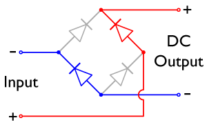
A diode bridge is an arrangement of four diodes connected in a bridge circuit as shown below, that provides the same polarity of output voltage for any polarity of the input voltage. When used in its most common application, for conversion of alternating current (AC) input into direct current (DC) output, it is known as a bridge rectifier. The diagram (using a popular schematic layout with the four diodes forming the sides of a diamond) describes one diode-bridge design, the full-wave rectifier or Graetz circuit. This design is used to rectify single phase AC when no transformer center tap is available.
The essential feature of this circuit is that for both polarities of the voltage between the bridge inputs, the polarity of the outputs is the same.
For example, when the input connected at the left corner of the diamond is positive with respect to the one connected at the right, current flows to the right across the upper colored path, and overall to the left across the lower one.
When the right input is positive relative to the left, current flow is overall diagonally up to the right, and diagonally up to the left.
In each of those cases, the top right output remains positive with respect to the lower right one. Since this is true whether the input is AC or DC, this circuit not only produces DC power when supplied with AC power: it also can provide what is sometimes called "reverse polarity protection". That is, it permits normal functioning when batteries are installed backwards or DC input-power supply wiring "has its wires crossed" (and protects the circuitry it powers against damage that might occur without this circuit in place).
Prior to availability of integrated electronics, such a bridge rectifier was always constructed from discrete components. Since about 1950, a single four-terminal component containing the four diodes connected in the bridge configuration became a standard commercial component and is now available with various voltage and current ratings.
For many applications, especially with single phase AC where the full-wave bridge serves to convert an AC input into a DC output, the addition of a capacitor may be important because the bridge alone supplies an output voltage of fixed polarity but pulsating magnitude (see photograph above).
The function of this capacitor, known as a 'smoothing capacitor' is to lessen the variation in (or 'smooth') the raw output voltage waveform from the bridge. One explanation of 'smoothing' is that the capacitor provides a low impedance path to the AC component of the output, reducing the AC voltage across, and AC current through, the resistive load. In less technical terms, any drop in the output voltage and current of the bridge tends to be cancelled by loss of charge in the capacitor. This charge flows out as additional current through the load. Thus the change of load current and voltage is reduced relative to what would occur without the capacitor. Increases of voltage correspondingly store excess charge in the capacitor, thus moderating the change in output voltage / current.
For three-phase AC, a full wave bridge rectifier consists of six diodes.


