This is an old revision of this page, as edited by DaveeBlahBlah (talk | contribs) at 01:45, 2 February 2014 (→Inductor coil: addition to section 'Inductor coil'). The present address (URL) is a permanent link to this revision, which may differ significantly from the current revision.
Revision as of 01:45, 2 February 2014 by DaveeBlahBlah (talk | contribs) (→Inductor coil: addition to section 'Inductor coil')(diff) ← Previous revision | Latest revision (diff) | Newer revision → (diff) For other uses, see Electromagnetic coil (disambiguation). "Winding" redirects here. For other uses, see Winding (disambiguation).
An electromagnetic coil (or simply a "coil") is formed when a conductor (usually an insulated solid copper wire) is wound around a core or form to create an inductor or electromagnet. When electricity is passed through a coil, it generates a magnetic field. One loop of wire is usually referred to as a turn or a winding, and a coil consists of one or more turns. For use in an electronic circuit, electrical connection terminals called taps are often connected to a coil. Coils are often coated with varnish or wrapped with insulating tape to provide additional insulation and secure them in place. A completed coil assembly with one or more set of coils and taps is often called the windings.
Windings are used in transformers, electric motors, inductors, solenoids, loudspeakers, and many other applications.
General principles

The conducting material used for the windings depends upon the application, but in all cases the individual turns must be electrically insulated from each other to ensure that the current travels throughout every turn. For small power and signal applications, in which currents are low and the potential difference between adjacent turns is small, the coils are often wound from enamelled magnet wire, such as Formvar wire. Larger power transformers operating at high voltages may be wound with copper rectangular strip conductors insulated by oil-impregnated paper and blocks of pressboard.

Effects of frequency
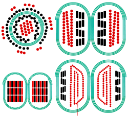
High-frequency coils operating in the tens to hundreds of kilohertz often have windings made of braided Litz wire to minimize the skin-effect and proximity effect losses. Large power transformers use multiple-stranded conductors as well, since even at low power frequencies non-uniform distribution of current would otherwise exist in high-current windings. Each strand is individually insulated, and the strands are arranged so that at certain points in the winding, or throughout the whole winding, each portion occupies different relative positions in the complete conductor. The transposition equalizes the current flowing in each strand of the conductor, and reduces eddy current losses in the low winding itself. The stranded conductor is also more flexible than a solid conductor of similar size, aiding manufacture.
The windings of signal coils minimize leakage inductance and stray capacitance to improve high-frequency response. Coils are split into sections, and those sections interleaved between the sections of the other winding.
Taps
Coils may have taps at intermediate points on the winding for various uses.
In transformers, taps may be manually reconnected, or a manual or automatic switch may be provided for changing taps. Automatic on-load tap changers are used in electric power transmission or distribution, on equipment such as arc furnace transformers, or for automatic voltage regulators for sensitive loads. Audio-frequency transformers, used for the distribution of audio to public address loudspeakers, have taps to allow adjustment of impedance to each speaker. A center-tapped transformer is often used in the output stage of an audio power amplifier in a push-pull circuit. Modulation transformers in AM transmitters are very similar.
Potting
Coils are often potted to prevent the wires from moving in use. Traditionally a shellac material was soaked into the windings after assembly and oven dried.
Dry-type coil winding insulation systems can be either of standard open-wound 'dip-and-bake' construction or of higher quality designs that include vacuum pressure impregnation (VPI), vacuum pressure encapsulation (VPE), and cast coil encapsulation processes. In the VPI process, a combination of heat, vacuum and pressure is used to thoroughly seal, bind, and eliminate entrained air voids in the winding polyester resin insulation coat layer, thus increasing resistance to corona. VPE windings are similar to VPI windings but provide more protection against environmental effects, such as from water, dirt or corrosive ambients, by multiple dips including typically in terms of final epoxy coat.
Construction of mdoil-filled transformers requires that the insulation covering the windings be thoroughly dried before the oil is introduced. Drying is carried out at the factory, and may be required as a field service. Drying may be done by circulating hot air around the core, or by vapour-phase drying (VPD) where evaporated solvent transfers heat by condensation on the coil and core. For small transformers resistance heating by injection of current into the windings is used. The heating can be controlled very well and it is energy efficient. The method is called low-frequency heating (LFH) since the current is injected at a much lower frequency than the nominal of the grid, which is normally 50 or 60 Hz. A lower frequency reduces the effect of the inductance in the transformer, so the voltage needed to induce the current can be reduced. The LFH drying method is also used for service of older transformers.
Capacitance
Coils, particularly multilayer coils can have interlayer capacitance.
When this capacitance is problematic multiple layers are often replaced with a single layer, as in a pancake coil, or a solenoid with a single layer is used.

Specific types
Solenoid
Main article: Solenoid
A solenoid (from the French solénoïde, derived in turn from the Greek solen "pipe, channel" + combining form of Greek eidos "form, shape") is a coil wound into a tightly packed helix. The term was invented by André-Marie Ampère to designate a helical coil.
In physics, the term refers specifically to a long, thin loop of wire, often wrapped around a metallic core, which produces a uniform magnetic field in a volume of space (where some experiment might be carried out) when an electric current is passed through it. Solenoids are important because they can create controlled magnetic fields and can be used as electromagnets.
In engineering, the term may also refer to a variety of transducer devices that convert energy into linear motion. The term is also often used to refer to a solenoid valve, which is an integrated device containing an electromechanical solenoid which actuates either a pneumatic or hydraulic valve, or a solenoid switch, which is a specific type of relay that internally uses an electromechanical solenoid to operate an electrical switch; for example, an automobile starter solenoid, or a linear solenoid, which is an electromechanical solenoid.
Transformers
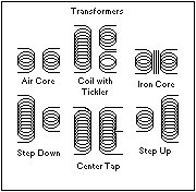
Main article: transformerA transformer is an electromagnetic device that has a primary winding and a secondary winding that transfers energy from one electrical circuit to another by inductive coupling without moving parts. The term tickler coil usually refers to a feedback coil, which is often the third coil placed in relation to a primary coil and secondary coil. A coil tap is a wiring feature found on some electrical transformers, inductors and coil pickups, all of which are sets of wire coils. The coil tap(s) are points in a wire coil where a conductive patch has been exposed (usually on a loop of wire that extends out of the main coil body).
Inductor coil
An inductor coil is typically a relatively simple two-terminal winding over a magnetic core. Usually, coils will have an air, iron, or power-iron core. Since the permeability of iron is far greater than the permeability of air, an inductor with an iron core has a greater inductance than an inductor with an air core. Inductors may have variable cores that slide in/out of the center of the coil. The core's travel distance into the coil determines the inductance.
Electric motor
Electric motor windings can be quite complex. They are often 3 phase design, with 3 sets of windings. Many different layouts, interleavings and windings are in use.
References
- Dixon, L.H., Jr. (1997). "Eddy Current Losses in Transformer Windings" (PDF). Texas Instrument: R2-1-to-R2-10.
{{cite journal}}: Cite journal requires|journal=(help)CS1 maint: multiple names: authors list (link) - ^ Central Electricity Generating Board (1982). Modern Power Station Practice. Pergamon Press.
- Dixon, Lloyd (2001). "Power Transformer Design" (PDF). Magnetics Design Handbook. Texas Instruments.
{{cite conference}}: Unknown parameter|booktitle=ignored (|book-title=suggested) (help) - Lane, Keith (2007). "The Basics of Large Dry-Type Transformers". EC&M. Retrieved 29 January 2013.
{{cite web}}: CS1 maint: numeric names: authors list (link) - Heathcote, pp. 720–723
- Fink, Donald G. (1978). Standard Handbook for Electrical Engineers (11th ed.). McGraw Hill. pp. 10-38 through 10-40. ISBN 978-0-07-020974-9.
{{cite book}}: Unknown parameter|coauthors=ignored (|author=suggested) (help) - Figueroa, Elisa; et al. (Jan/Feb 2009). "Low Frequency Heating Field Dry-Out of a 750 MVA 500 kV Auto Transformer" (PDF). Electricity Today. Retrieved Feb 28, 2012.
{{cite web}}: Check date values in:|date=(help); Explicit use of et al. in:|first=(help) - "Solenoid". Online Etymology Dictionary.
- "Parcours pédagogique — Ampère et l'histoire de l'électricité". CNRS. Retrieved July 31, 2012.
Further reading
- Querfurth, William, "Coil winding; a description of coil winding procedures, winding machines and associated equipment for the electronic industry" (2d ed.). Chicago, G. Stevens Mfg. Co., 1958.
- Weymouth, F. Marten, "Drum armatures and commutators (theory and practice) : a complete treatise on the theory and construction of drum winding, and of commutators for closed-coil armatures, together with a full résumé of some of the principal points involved in their design; and an exposition of armature reactions and sparking". London, "The Electrician" Printing and Publishing Co., 1893.
- "Coil winding proceedings". International Coil Winding Association.
- Chandler, R. H., "Coil coating review, 1970-76". Braintree, R. H. Chandler Ltd, 1977.
External links
- R. Clarke, "Producing wound components". Surrey.ac.uk, 2005 October 9
| Electric machines | |
|---|---|
| |
| Components and accessories | |
| Generators | |
| Motors | |
| Motor controllers | |
| History, education, recreational use | |
| Experimental, futuristic | |
| Related topics | |
| People | |