This is an old revision of this page, as edited by Spinningspark (talk | contribs) at 23:53, 9 September 2014 (→Power transmission: correct link to pole-mount transformer. Remove wikilink to Canada (WP:OVERLINK)). The present address (URL) is a permanent link to this revision, which may differ significantly from the current revision.
Revision as of 23:53, 9 September 2014 by Spinningspark (talk | contribs) (→Power transmission: correct link to pole-mount transformer. Remove wikilink to Canada (WP:OVERLINK))(diff) ← Previous revision | Latest revision (diff) | Newer revision → (diff)- This article is about the electrical transmission line. For the American football offensive line, see glossary of American football. For three-phase electric power lines carrying unbalanced currents see Three-phase electric power#Unbalanced loads.

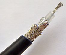
In electrical engineering, an unbalanced line is a transmission line, often coaxial cable, whose conductors have unequal impedances with respect to ground; as opposed to a balanced line. Microstrip and single-wire lines are also unbalanced lines.
General description
Any line that has a different impedance of the return path may be considered an unbalanced line. However, unbalanced lines usually consist of a conductor that is considered the signal line and another conductor that is grounded, or is ground itself. The ground conductor often takes the form of a ground plane or the screen of a cable. The ground conductor may be, and often is, common to multiple independent circuits. For this reason the ground conductor may be referred to as common.
Telegraph lines

The earliest use of unbalanced transmission lines was for electric telegraph communications. These consisted of single wires strung between poles. The return path for the current was originally provided by a separate conductor. Some early telegraph systems, such as Schilling's experimental needle telegraph (1832) and the Cooke & Wheatstone five-needle telegraph (1837) used by British raliways required multiple code wires. Essentially, they were parallel bus coding. In these systems the cost of the return conductor was not so significant (one conductor in seven for Schilling's earliest needle telegraph and one conductor in six for the Cooke and Wheatstone telegraph) but the number of coding conductors was progressively reduced with improved systems. Soon only one coding wire was required with the data being transmitted serially. Important examples of these single-wire systems were the Morse telegraph (1837) and the Cooke & Wheatstone single-needle telegraph (1843). In such systems the cost of a return conductor was fully 50 per cent of the cable costs. It was discovered that a return conductor could be replaced with a return path through the Earth using grounding spikes. Using earth return was a significant cost saving and rapidly became the norm.
Underground telegraph cables into large buildings or between stations often needed to carry multiple independent telegraph lines. These cables took the form of multiple insulated conductors enclosed by a metal screen and overall protective jacket. In such cables the screen can be used as the return conductor. Undersea telegraph cables were usually a single conductor protected by steel-wire armour, effectively a coaxial cable. The first transatlantic cable of this kind was completed in 1866.
Early telephone lines (telephone invented 1876) initially used the same transmission line scheme as telegraph of unbalanced single wires. However, telephone communication started to suffer after the widespread introduction of electrical power lines. Telephone transmission started to use balanced lines to combat this problem and the modern norm for telephone presentation is the balanced twisted pair cable.
Coaxial lines

A coaxial line (coax) has a central signal conductor surrounded by a cylindrical shielding conductor. The shield conductor is normally grounded. The coaxial format was developed during World War 2 for use in radar. It was originally constructed from rigid copper pipes, but the usual form today is a flexible cable with a braided screen. The advantages of coax are a theoretically perfect electrostatic screen and highly predictable transmission parameters. The latter is a result of the fixed geometry of the format which leads to a precision not found with loose wires. Open wire systems are also affected by nearby objects altering the field pattern around the conductor. Coax does not suffer from this since the field is entirely contained within the cable due to the surrounding screen.
Coaxial lines are the norm for connections between radio transmitters and their antennae, for interconnection of electronic equipment where high frequency or above is involved, and were formerly widely used for forming local area networks before twisted pair became popular for this purpose.
Triaxial cable (triax) is a variant of coax with a second shield conductor surrounding the first with a layer of insulation in between. As well as providing additional shielding, the outer conductors can be used for other purposes such as providing power to equipment or control signals. Triax is widely used for the connection of cameras in television studios.
Planar technologies
Power transmission

References
- Huurdeman, p. 54
- Huurdeman, p. 67
Bibliography
- Huurdeman, Anton A., The Worldwide History of Telecommunications, John Wiley & Sons, 2003 ISBN 0471205052.