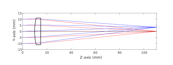
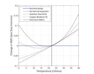
Athermalization, in the field of optics, is the process of achieving optothermal stability in optomechanical systems. This is done by minimizing variations in optical performance over a range of temperatures.
Optomechanical systems are typically made of several materials with different thermal properties. These materials compose the optics (refractive or reflective elements) and the mechanics (optical mounts and system housing). As the temperature of these materials change, the volume and index of refraction will change as well, increasing strain and aberration content (primarily defocus). Compensating for optical variations over a temperature range is known as athermalizing a system in optical engineering.

Material property changes

Thermal expansion is the driving phenomena for the extensive and intensive property changes in an optomechanical system.
Extensive properties
Extensive property changes, such as volume, alter the shape of optical and mechanical components. Systems are geometrically optimized for optical performance and are sensitive to components changing shape and orientation. While volume is a three dimensional parameter, thermal changes can be modeled in a single dimension with linear expansion, assuming an adequately small temperature range. For examples, glass manufacturer Schott provides the coefficient of linear thermal expansion for a temperature range of -30 C to 70 C. The change in length of a material is a function of the change in temperature with respect to the standard measurement temperature, . This temperature is typically room temperature or 22 degrees Celsius.
Where is the length of a material at temperature , is the length of the material at temperature , is the change in temperature, and is the coefficient of thermal expansion. These equations describe how diameter, thickness, radius of curvature, and element spacing change as a function of temperature.
Intensive properties

The dominant intensive property change, in terms of optical performance, is the index of refraction. The refractive index of glass is a function of wavelength and temperature. There are multiple formulas that can be used to define the wavelength dependence, or dispersion, of a glass. Following the notation from Schott, the empirical Sellmeier equation is shown below.

Where is wavelength and , , , , , and are the Sellmeier coefficients. These coefficients can be found in glass catalogs provided from manufacturers and are usually valid from the near-ultraviolet to the near-infrared. For wavelengths beyond this range, it is necessary to know the material's transmittance with respect to wavelength. From the dispersion formula, the temperature dependence of refractive index can be written:
and
Where , , , , , and are glass-dependent constants for an optic in vacuum. The power of an optic as a function of temperature can be written from the equations for extensive and intensive property changes, in addition to the lensmaker's equation.
Where is optical power, is the radius of curvature, is the thickness of the lens. These equations assume spherical surfaces of curvature. If a system is not in vacuum, the index of refraction for air will vary with temperature and pressure according to the Ciddor equation, a modified version of the Edlén equation.

Athermalization techniques
To account for optical variations introduced by extensive and intensive property changes in materials, systems can be athermalized through material selection or feedback loops.
Passive athermalization
Passive athermalization works by choosing materials for a system that will compensate the overall change in system performance. The simplest way to do this is to choose materials for the optics and mechanics which have low CTE and values. This technique is not always possible as glass types are primarily chosen based on their refractive index and dispersion characteristics at operating temperature. Alternatively, mechanical materials can be chosen which have CTE values complementary to the change in focus introduced by the optics. A material with the preferred CTE is not always available, so two materials can be used in conjunction to effectively get the desired CTE value. Negative thermal expansion materials have recently increased the range of potential CTEs available, expanding passive athermalization options.
Active athermalization
When optical designs do not permit the selection of materials based on their thermal characteristics, passive athermalization may not be a viable technique. For example, the use of germanium in mid to long wave infrared systems is common because of its exceptional optical properties (high index of refraction and low dispersion). Unfortunately, germanium is also known for its large value, which makes it difficult to passively athermalize.
Because the primary aberration induced by temperature change is defocus, an optical element, group, or focal plane can be mechanically moved to refocus a system and account for thermal changes. Actively athermalized systems are designed with a feedback loop including a motor, for the focusing mechanism, and temperature sensor, to indicate the magnitude of the focus adjustment.
Temperature gradients
When a system is not in thermal equilibrium, it complicates the process of determining system performance. A common temperature gradient to encounter is an axial gradient. This involves temperatures changing in a lens as a function of the thickness of the lens, or often along the optical axis. In optical lens design it is standard notation for the optical axis to be co-linear with the Z-axis in cartesian coordinates. A difference between the temperature of the first and second surface of a lens will cause the lens to bend. This affects each radius of curvature, therefor changing the optical power of the lens. The radius of curvature change is a function of the temperature gradient in the optic.
Where is the thickness of the lens. Radial gradients are less predictable as they may cause the shape of curvature to change, making spherical surfaces aspherical. Determining temperature gradients in an optomechanical system can quickly become an arduous task, requiring an intimate understanding of the heat sources and sinks in a system. Temperature gradients are determined by heat flow and can be a result of conduction, convection, or radiation. Whether steady-state or transient solutions are adequate for an analysis is determined by operating requirements, system design, and the environment. It can be beneficial to leverage the computational power of the finite element method to solve the applicable heat flow equations to determine the temperature gradients of optical and mechanical components.
External links
- Refractive index of air calculator
- Table of common material CTE values
- Information on glass from Schott
- Information on glass from Hoya
- Information on glass from Ohara
- Information on glass from CDGM
References
- ^ Bentley & Olson (2012). Field Guide to Lens Design. Bellingham, Washington USA: SPIE. p. 88. ISBN 978-0-8194-9164-0.
- Kenichi Iga; Yasuo Kokubun (1 November 2005). Encyclopedic Handbook of Integrated Optics. CRC Press. pp. 32–. ISBN 978-1-4200-2781-5.
- Jamieson (1981). "Thermal effects in optical systems" (PDF). Optical Engineering. 20 (2): 156. Bibcode:1981OptEn..20..156J. doi:10.1117/12.7972683. Retrieved 8 December 2020.
- ^ "Refractive Index and Dispersion" (PDF). us.schott.com. Schott AG. Retrieved 13 December 2020.
- ^ "Optical Glass Data Sheets" (PDF). www.schott.com. Schott AG. Retrieved 6 December 2020.
- ^ "Temperature Coefficient of the Refractive Index" (PDF). www.schott.com. Schott AG. Retrieved 7 December 2020.
- "Temperature Coefficient of Refractive Index (dn/dT)". www.pmoptics.com. Precision Micro-Optics. Retrieved 7 December 2020.
- Birch & Downs (1993). "An Updated Edlen Equation for the Refractive Index of Air". Metrologia. 30 (3): 155–162. Bibcode:1993Metro..30..155B. doi:10.1088/0026-1394/30/3/004. S2CID 250817121.
- Stone & Zimmerman. "Edlen or Ciddor? Guidance in Choosing the Equation". emtoolbox.nist.gov. National Institute of Standards and Technology. Retrieved 13 December 2020.
- ^ Schwertz & Burge (2012). Field Guide to Optomechanical Design and Analysis. Bellingham, Washington USA: SPIE. pp. 98–105. ISBN 978-0-8194-9161-9.
- Monroe, James A.; McAllister, Jeremy S.; Content, David; Zgarba, Jay (19 February 2020). "Negative thermal expansion ALLVAR Alloys for smaller optics". In Kress, Bernard C.; Peroz, Christophe (eds.). Optical Architectures for Displays and Sensing in Augmented, Virtual, and Mixed Reality (AR, VR, MR). Vol. 11310. pp. 296–303. Bibcode:2020SPIE11310E..13M. doi:10.1117/12.2546869. ISBN 9781510633872. S2CID 213607039.
- "Germanium". www.pmoptics.com. Precision Micro-Optics. Retrieved 14 December 2020.
- ^ Bayar & Farsakoğlu (2002). "Mechanically active athermalization of a forward looking infrared system". Infrared Physics & Technology. 43 (2): 91–99. Bibcode:2002InPhT..43...91B. doi:10.1016/S1350-4495(01)00124-4.
 . This temperature is typically

 is the length of a material at temperature
  ,
,  is the length of the material at temperature
  is the change in temperature, and
  is the coefficient of thermal expansion. These equations describe how
 is wavelength and
  ,
,  ,
,  ,
,  ,
,  , and
, and  are the Sellmeier coefficients. These coefficients can be found in glass catalogs provided from manufacturers and are usually valid from the near-

 ,
,  ,
,  ,
,  ,
,  , and
, and  are glass-dependent constants for an optic in

 is
is  is the radius of curvature,
  is the thickness of the lens. These equations assume
  values. This technique is not always possible as glass types are primarily chosen based on their refractive index and dispersion characteristics at operating temperature. Alternatively, mechanical materials can be chosen which have CTE values complementary to the change in focus introduced by the optics. A material with the preferred CTE is not always available, so two materials can be used in conjunction to effectively get the desired CTE value.