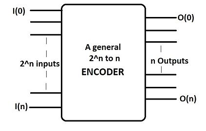
An encoder (or "simple encoder") in digital electronics is a one-hot to binary converter. That is, if there are 2 input lines, and at most only one of them will ever be high, the binary code of this 'hot' line is produced on the n-bit output lines. A binary encoder is the dual of a binary decoder.
If the input circuit can guarantee at most a single-active input, a simple encoder is a better choice than a priority encoder, since it requires less logic to implement. However, a simple encoder can generate an incorrect output when more than a single input is active, so a priority encoder is required in such cases.
Types of encoder
2-to-n encoders
A -to-n encoder has n number of outputs in correspondence to the number of inputs. It thus reduces the number of transmission lines and can be compared to a multiplexer. Only one of the inputs become "high" (logic state "1") at a time.
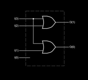
For example, a 4-to-2 simple encoder takes 4 input bits and produces 2 output bits. The illustrated gate level example implements the simple encoder defined by the truth table, but it must be understood that for all the non-explicitly defined input combinations (i.e., inputs containing 0, 2, 3, or 4 high bits) the outputs are treated as don't cares.
4-to-2 encoder

| Input | Output | |||||
| I3 | I2 | I1 | I0 | O1 | O0 | |
| 0 | 0 | 0 | 0 | x | ||
| 0 | 0 | 0 | 1 | 0 | 0 | |
| 0 | 0 | 1 | 0 | 0 | 1 | |
| 0 | 1 | 0 | 0 | 1 | 0 | |
| 1 | 0 | 0 | 0 | 1 | 1 | |
8-to-3 encoder

| Input | Output | |||||||||
| I7 | I6 | I5 | I4 | I3 | I2 | I1 | I0 | O2 | O1 | O0 |
| 0 | 0 | 0 | 0 | 0 | 0 | 0 | 0 | x | ||
| 0 | 0 | 0 | 0 | 0 | 0 | 0 | 1 | 0 | 0 | 0 |
| 0 | 0 | 0 | 0 | 0 | 0 | 1 | 0 | 0 | 0 | 1 |
| 0 | 0 | 0 | 0 | 0 | 1 | 0 | 0 | 0 | 1 | 0 |
| 0 | 0 | 0 | 0 | 1 | 0 | 0 | 0 | 0 | 1 | 1 |
| 0 | 0 | 0 | 1 | 0 | 0 | 0 | 0 | 1 | 0 | 0 |
| 0 | 0 | 1 | 0 | 0 | 0 | 0 | 0 | 1 | 0 | 1 |
| 0 | 1 | 0 | 0 | 0 | 0 | 0 | 0 | 1 | 1 | 0 |
| 1 | 0 | 0 | 0 | 0 | 0 | 0 | 0 | 1 | 1 | 1 |
See also
References
- "Binary Encoders And Their Applications". Electronics Hub. 2015-06-29. Retrieved 2017-05-01.
 -to-n encoder has n number of outputs in correspondence to the