| This article needs additional citations for verification. Please help improve this article by adding citations to reliable sources. Unsourced material may be challenged and removed. Find sources: "Continuous-rod warhead" – news · newspapers · books · scholar · JSTOR (July 2007) (Learn how and when to remove this message) |

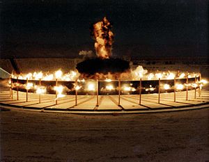
A continuous-rod warhead is a specialized munition exhibiting an annular blast fragmentation pattern, thus when exploding it spreads into a large circle cutting through the target. It is used in anti-aircraft and anti-missile missiles.
Early anti-aircraft munitions
Rifle and machine-gun bullets were used against early military aircraft during World War I. Artillery was used when aircraft flew above the range of rifle and machine-gun cartridges. Since the probability of actually striking the aircraft was small, artillery shells were designed to explode at the approximate altitude of the aircraft to throw a shower of fragments in the vicinity of the explosion. Similar anti-aircraft weaponry with larger calibers, higher rates of fire, and improved fuzes continued to be used through World War II. These bullets and small fragments often made small holes in the airframe. Unless a bullet or fragment struck the pilot, or some critical part of the airframe, (like a fuel line, part of the engine coolant system, a critical wire or hydraulic line actuating control surfaces), the aircraft remained operational. Some anti-aircraft artillery projectiles were designed to fragment into long, thin pieces in an attempt to inflict damage on the airframe. Holes made by such fragments were more likely to cause destructive disruption of airflow around high-speed aircraft, but the hit probability was lowered for the smaller number of fragments from a warhead of equal size.
The problem became more significant as anti-aircraft missiles were developed to replace guns after World War II: A smaller number of missiles would require an improved warhead to match the aircraft destruction probability of the larger number of artillery projectiles potentially carried by a weapon of the same size and cost.
The concept of a folded continuous rod warhead was suggested in 1952. The Applied Physics Laboratory of Johns Hopkins University invented the Continuous Expanding Rod Warhead as part of its Navy-contracted development of the U. S. Navy's anti-air missile defense program. The details of the warhead were Top Secret until its use was no longer needed.
Construction
An even number of individual steel rods are arranged in parallel to form a cylinder. The ends of the rods are welded together—the first rod and the second rod are welded together at the top, the second and third at the bottom, and so on all the way around the form.
-
 Rods arranged on mandrel prior to welding (single layer shown)
-
 Alternating welds completed and ready to receive explosives
-
 Representation of rod expansion due to detonation of explosives
-
 Use and effects (exaggerated)
Operation

When detonated, the high explosive imparts momentum to the rods, thrusting them outward in an expanding circle. The pressure wave from the explosive needs to act evenly on the rods over their length, so some sort of tamper is used to shape the shock wave similar to an explosive lens. The rods are sufficiently soft (ductile) to allow the expansion without breaking the rods or the welded joints, and the detonation velocity is limited to under 1,150 m/s, allowing the rods to bend at these locations instead. At some intermediate point the ring will have a zig-zag (alternating direction) appearance within a cylindrical envelope. Upon ultimate expansion the ring is circular and contained within a plane. The ring will then break and ultimately tend to form one or more straight rods. Since the net momentum of the rod relative to the missile is roughly zero, its effectiveness will rapidly diminish as the broken ring expands.
This rapidly expanding ring, when hitting the aircraft, can be more effective than an equivalent fragmentation warhead: the ring of rods provides a larger surface area than a fragmented ballistic. Portions of the aircraft intercepted by the expanding ring of the continuous rod warhead will receive a continuous cut through the skin, flight or aerodynamic surfaces, underlying cables, hydraulic lines, and other flight or mission-critical structures. This may cause a structural failure, or, if not, can be sufficient for defeating the redundancy of aircraft systems. The effect is only pronounced as long as the ring is unbroken, so multiple layers of rods are employed in practical weapons to increase the effective radius.
When designing the ill-fated SAM-equipped Mauler, Monte Carlo simulations on the then-state-of-the-art IBM 650 indicated that a continuous-rod warhead was likely to be less effective than blast fragmentation types. Subsequent implementations indicated the opposite.
References
- "Talos Missile Warhead History". Retrieved 2011-01-27.
- ^ "Fundamentals of Naval Weapons Systems". Retrieved 2011-05-15.
- Payne, Craig M. (2006-12-08). Principles of Naval Weapon Systems. Naval Institute Press. p. 352. ISBN 978-1-59114-658-2.
- Margolin, M, J, et al. "Warheads for Mauler Weapon System", US Army, Pictinny Arsenal, report PATM-137B46-(A57)-Vol-2, 1 November 1958