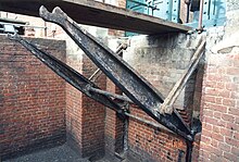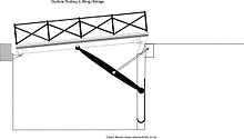
A Guthrie rolling bridge was a kind of retractable bridge, an 18th-century version of the drawbridge. It was commonly installed as the access across the narrow steep sided ditches characteristic of the polygonal forts of this era.
Rolling bridges were unhinged, and remained horizontal as they were retracted within the gates of a fortification, similar in operation to a modern thrust bridge.
Running the bridge out
Running the bridge out is effected by pushing it along its rails until the outer two wheels are at the edge of the granite sill of the ditch. When the bridge is pushed beyond this point the two outer wheels do not descend the slopes of the granite slabs but instead the bridge remains in a horizontal position. This is due to the centre axle being offset from the centre of the girders causing the bridge to run on its inner two wheels. The middle two wheels follow along the trays.
When the bridge is just less than halfway out, the ends of the centre axle then engage in the cups of the lifting arms. The middle two wheels partially descend the slopes of the granite sill. The bridge continues to move out, its outer end dipping below the horizontal, its inner wheels still running along the trays of the courtyard. The weight of the bridge, at the point where the centre of gravity of the lifting arms is beyond the pivot point of the arms and the stays, causes the bridge mechanism to descend, its wheels running up the vertical racers set into the wall of the pit.
At a point where the inner wheels are at the top of the slope down the granite sill, the outer ends of the girders and the outer wheels hit curved sprung metal guides. These guide the outer end of the bridge upwards so that the ends of the girders come to rest on the lip of the granite slab, the inner wheels descending the slope of the inner granite slab. The inner end of each girder is angled to form a close fit with the granite slab.
Running the bridge in

To raise the bridge an initial lift to the inner end of the bridge is required. This raises the inner wheels back up the inclines of the granite slabs. At the same time the outer ends are pulled from the lip of the granite slab, the wheels rolling down the sprung metal guides. When the inner wheels are pulled up onto the metal trays the weight of the lifting arms assists the raising of the bridge to a point where the centre of gravity of the arms is over the pivot of the upper support stays. From here on the pull necessary to raise the centre wheels is negligible. Once the lifting arms are in the fully retracted position the centre wheels are on top of the metal trays and the axles disengage from the cups. The bridge now sits on its inner two axles. From here it is necessary to pull the bridge in until the outer two wheels arrive at the trays. The bridge is then pulled within the gates on all six wheels.
The bridge adopted by the military
Director of Artillery 8/8/70 forwards for record a correspondence, as follows:
Director of Works 18/08/69 submits a claim from Mr. Guthrie for some recognition of his services on account of his invention of a rolling bridge applicable to defensive works. Colonel Jervois states that this bridge has been adopted with success in several of the forts recently constructed. The subject was considered at a meeting of the Ordnance Council held at War Office 9/ 7/69, and it was resolved to recommend the grant of 100l. to Mr. Guthrie. The Lords of the Treasury, 138/69, sanctioned the above, on the understanding that the invention had been carried out during unofficial hours. Mr. Guthrie, 13/9/69 stated that such was the case. A sum of 100l was inserted in the Army Estimates for 1870-71 as a reward to Mr. Guthrie; sanctioned by Parliament; and claim allowed, 27/07/70
Locations
Bridges of this type were fitted to the forts of the Portsdown Hill line at Portsmouth. The lifting arms of both bridges survive at Fort Nelson, Portsmouth, United Kingdom. Other locations at which the bridge was installed include Cambridge Battery and Rinella Battery in Malta. The remains of another Guthrie bridge was discovered at the main caponier of The Verne Citadel at Portland, Dorset, during research conducted by The Palmerston Forts Society and Hampshire County Council Architects for restoration work on the bridges at Fort Nelson.
See also
References
- Guthrie’s Rolling Bridge by David Moore The Redan no. 26 October 1992: Journal of The Plamerston Forts Society
- Guthrie’s Rolling Bridge by David Moore ibid
- National Archive WO33/2/A
- Fort Nelson and the Portsdown Forts by Garry Mitchell: Solent Papers No.3 ISBN 0-9513234-5-8
External links
- Victorian Forts data sheet on Fort Nelson Archived 2012-05-30 at the Wayback Machine
| Bridge-related articles | ||
|---|---|---|
| Structural types |
|  |
| Lists of bridges by type | ||
| Lists of bridges by size | ||
| Additional lists | ||
| Related | ||