| This article is an orphan, as no other articles link to it. Please introduce links to this page from related articles; try the Find link tool for suggestions. (August 2024) |

Heat flux measurements of thermal insulation are applied in laboratory and industrial environments to obtain reference or in-situ measurements of the thermal properties of an insulation material. Thermal insulation is tested using nondestructive testing techniques relying on heat flux sensors. Procedures and requirements for in-situ measurements are standardized in ASTM C1041 standard: "Standard Practice for In-Situ Measurements of Heat Flux in Industrial Thermal Insulation Using Heat Flux Transducers".
Laboratory methods
| This section is empty. You can help by adding to it. (August 2018) |
On-site methods

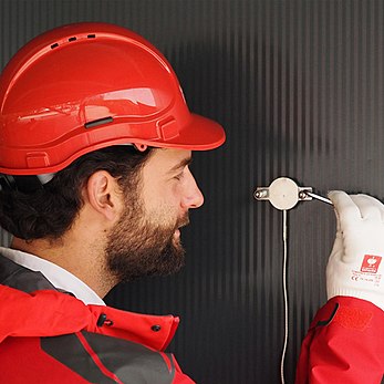
On-site heat flux measurements are often focused on testing the thermal transport properties of for example pipes, tanks, ovens and boilers, by calculating the heat flux q or the apparent thermal conductivity . The real-time energy gain or loss is measured under pseudo steady state-conditions with minimal disturbance by a heat flux transducer (HFT). This on-site method is for flat surfaces (non-pipes) only.
Measurement procedure
- Placement of the HFT:
- The sensor should be placed on an area of insulation that represents the overall system. For example, it should not be placed closed to an inlet or outlet of a boiler or near a heating element.
- Shield the sensor from other sources of heat flux that are not relevant to the measurement, e.g. solar radiation.
- Make sure that the HFT is connected to the insulation surface via thermal paste or other conductive material. The emittance of the HFT should match the emittance of surface as close as possible. Air or other material between the sensor and the surface of measurement could lead to measurement errors.
- Pre-measurements:
- Measure the thickness of the insulation material to the nearest millimetre.
- Log ambient weather conditions if necessary. Humidity, air movement and precipitation may be of interest for the interpretation of the results
- Measure the temperature of the insulation surface near the sensor and the temperature at the inside of the insulation material, i.e. the process surface.
After successful application of these preparations connect the sensor to a datalogger or integrating voltmeter and wait until pseudo steady-state is achieved. It is advised to average the readings over a short time period when steady-state is achieved. This voltage measurement is the final measurement, but for good measure these steps should be applied on multiple relevant locations on the insulation.
Calculation and precision
The heat flux can be calculated from the voltage by:
- V is the voltage measured by the HFT (measured in volt, V)
- S is the sensitivity of the HFT (measured in volt / watt per square meter )
The apparent thermal conductivity can be calculated from:
- q is the heat flux calculated from the HFT (measured in watt per square meter, )
- D is the thickness of the insulation material (measured in millimeter, mm)
- the temperature of the process surface, the inside of the material
- the temperature of the surface near the HFT, the outside of the material
The interpretation and precision of the results depends on the section of measurement, the choice of HFT and external conditions. The correct heat flux sensor and measurement test section are of importance for a good in-situ measurement and should be based on manufacturer recommendations, past experience and careful consideration of the testing area.
Standards
ASTM C1041: Standard Practice for In-Situ Measurements of Heat Flux in Industrial Thermal Insulation Using Heat Flux Transducers
See also
References
- "ASTM C1041 - 10 Standard Practice for In-Situ Measurements of Heat Flux in Industrial Thermal Insulation Using Heat Flux Transducers (Withdrawn 2019)". Archived from the original on 2018-05-16. Retrieved 2018-05-15.
Bibliography
- Johannesson, G., “Heat Flow Measurements, Thermoelectrical Meters, Function Principles, and Sources of Error”, Division of Building Technology, Lund Institute of Technology, Report TUBH-3003, Lund,
Sweden, 1979. (Draft Translation, March 1982, U.S. Army Corps of Engineers)
- Poppendiek, H. F., “Why Not Measure Heat Flux Directly?”, Environmental Quarterly 15, No. 1, March 1, 1969.
- Gilbo, C. F., “Conductimeters, Their Construction and Use”, ASTM Bulletin No. 212, February, 1956.
 . The real-time energy gain or loss is measured under pseudo
  can be calculated from the voltage by:

 )
)
 )
) the temperature of the process surface, the inside of the material
 the temperature of the surface near the HFT, the outside of the material