The impulse excitation technique (IET) is a non-destructive material characterization technique to determine the elastic properties and internal friction of a material of interest. It measures the resonant frequencies in order to calculate the Young's modulus, shear modulus, Poisson's ratio and internal friction of predefined shapes like rectangular bars, cylindrical rods and disc shaped samples. The measurements can be performed at room temperature or at elevated temperatures (up to 1700 °C) under different atmospheres.
The measurement principle is based on tapping the sample with a small projectile and recording the induced vibration signal with a piezoelectric sensor, microphone, laser vibrometer or accelerometer. To optimize the results a microphone or a laser vibrometer can be used as there is no contact between the test-piece and the sensor. Laser vibrometers are preferred to measure signals in vacuum. Afterwards, the acquired vibration signal in the time domain is converted to the frequency domain by a fast Fourier transformation. Dedicated software will determine the resonant frequency with high accuracy to calculate the elastic properties based on the classical beam theory.
Elastic properties
Different resonant frequencies can be excited dependent on the position of the support wires, the mechanical impulse and the microphone. The two most important resonant frequencies are the flexural which is controlled by the Young's modulus of the sample and the torsional which is controlled by the shear modulus for isotropic materials.
For predefined shapes like rectangular bars, discs, rods and grinding wheels, dedicated software calculates the sample's elastic properties using the sample dimensions, weight and resonant frequency (ASTM E1876-15).
Flexure mode
The first figure gives an example of a test-piece vibrating in the flexure mode. This induced vibration is also referred as the out-of-plane vibration mode. The in-plane vibration will be excited by turning the sample 90° on the axis parallel to its length. The natural frequency of this flexural vibration mode is characteristic for the dynamic Young's modulus. To minimize the damping of the test-piece, it has to be supported at the nodes where the vibration amplitude is zero. The test-piece is mechanically excited at one of the anti-nodes to cause maximum vibration.
Torsion mode
The second figure gives an example of a test-piece vibrating in the torsion mode. The natural frequency of this vibration is characteristic for the shear modulus. To minimize the damping of the test-piece, it has to be supported at the center of both axis. The mechanical excitation has to be performed in one corner in order to twist the beam rather than flexing it.
Poisson's ratio
The Poisson's ratio is a measure in which a material tends to expand in directions perpendicular to the direction of compression. After measuring the Young's modulus and the shear modulus, dedicated software determines the Poisson's ratio using Hooke's law which can only be applied to isotropic materials according to the different standards.
Internal friction / Damping
Material damping or internal friction is characterized by the decay of the vibration amplitude of the sample in free vibration as the logarithmic decrement. The damping behaviour originates from anelastic processes occurring in a strained solid i.e. thermoelastic damping, magnetic damping, viscous damping, defect damping, ... For example, different materials defects (dislocations, vacancies, ...) can contribute to an increase in the internal friction between the vibrating defects and the neighboring regions.
Dynamic vs. static methods
Considering the importance of elastic properties for design and engineering applications, a number of experimental techniques are developed and these can be classified into 2 groups; static and dynamic methods. Statics methods (like the four-point bending test and nanoindentation) are based on direct measurements of stresses and strains during mechanical tests. Dynamic methods (like ultrasound spectroscopy and impulse excitation technique) provide an advantage over static methods because the measurements are relatively quick and simple and involve small elastic strains. Therefore, IET is very suitable for porous and brittle materials like ceramics and refractories. The technique can also be easily modified for high temperature experiments and only a small amount of material needs to be available.
Accuracy and uncertainty
The most important parameters to define the measurement uncertainty are the mass and dimensions of the sample. Therefore, each parameter has to be measured (and prepared) to a level of accuracy of 0.1%. Especially, the sample thickness is most critical (third power in the equation for Young's modulus). In that case, an overall accuracy of 1% can be obtained practically in most applications.
Applications
The impulse excitation technique can be used in a wide range of applications. Nowadays, IET equipment can perform measurements between −50 °C and 1700 °C in different atmospheres (air, inert, vacuum). IET is mostly used in research and as quality control tool to study the transitions as function of time and temperature. A detailed insight into the material crystal structure can be obtained by studying the elastic and damping properties. For example, the interaction of dislocations and point defects in carbon steels are studied. Also the material damage accumulated during a thermal shock treatment can be determined for refractory materials. This can be an advantage in understanding the physical properties of certain materials. Finally, the technique can be used to check the quality of systems. In this case, a reference piece is required to obtain a reference frequency spectrum. Engine blocks for example can be tested by tapping them and comparing the recorded signal with a pre-recorded signal of a reference engine block. By using simple cluster analysis algorithms or principal component analysis, sample's pattern recognition is also achievable with a set of pre-recorded signals.
Experimental correlations
Rectangular bar
Young's modulus
with
- E the Young's modulus
- m the mass
- ff the flexural frequency
- b the width
- L the length
- t the thickness
- T the correction factor
- The correction factor can only be used if L/t ≥ 20!
Shear modulus
with
- Note that we assume that b≥t
G the shear modulus
- ft the torsional frequency
- m the mass
- b the width
- L the length
- t the thickness
- R the correction factor
Cylindrical rod
Young's modulus
with
- E the Young's modulus
- m the mass
- ff the flexural frequency
- d the diameter
- L the length
- T' the correction factor
- The correction factor can only be used if L/d ≥ 20!
Shear modulus
with
- ft the torsional frequency
- m the mass
- d the diameter
- L the length
Poisson ratio
If the Young's modulus and shear modulus are known, the Poisson's ratio can be calculated according to:
Damping coefficient
The induced vibration signal (in the time domain) is fitted as a sum of exponentially damped sinusoidal functions according to:

with
- f the natural frequency
- δ = kt the logarithmic decrement
- In this case, the damping parameter Q can be defined as:
- with W the energy of the system
Extended IET applications: the Resonalyser Method
Isotropic versus orthotropic material behaviour
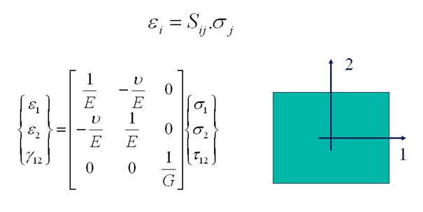
Isotropic elastic properties can be found by IET using the above described empirical formulas for the Young's modulus E, the shear modulus G and Poisson's ratio v. For isotropic materials the relation between strains and stresses in any point of flat sheets is given by the flexibility matrix in the following expression:
In this expression, ε1 and ε2 are normal strains in the 1- and 2-direction and Υ12 is the shear strain. σ1 and σ2 are the normal stresses and τ12 is the shear stress. The orientation of the axes 1 and 2 in the above figure is arbitrary. This means that the values for E, G and v are the same in any material direction.
More complex material behaviour like orthotropic material behaviour can be identified by extended IET procedures. A material is called orthotropic when the elastic properties are symmetric with respect to a rectangular Cartesian system of axes. In case of a two dimensional state of stress, like in thin sheets, the stress-strain relations for orthotropic material become:
E1 and E2 are the Young's moduli in the 1- and 2-direction and G12 is the in-plane shear modulus. v12 is the major Poisson's ratio and v21 is the minor Poisson's ratio. The flexibility matrix is symmetric. The minor Poisson's ratio can hence be found if E1, E2 and v12 are known.
The figure above shows some examples of common orthotropic materials: layered uni-directionally reinforced composites with fiber directions parallel to the plate edges, layered bi-directionally reinforced composites, short fiber reinforced composites with preference directions (like wooden particle boards), plastics with preference orientation, rolled metal sheets, and much more...
Extended IET for orthotropic material behaviour
Standard methods for the identification of the two Young's moduli E1 and E2 require two tensile, bending of IET tests, one on a beam cut along the 1-direction and one on a beam cut along the 2-direction. Major and minor Poisson's ratios can be identified if also the transverse strains are measured during the tensile tests. The identification of the in-plane shear modulus requires an additional in plane shearing test.
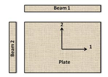
The "Resonalyser procedure" is an extension of the IET using an inverse method (also called "Mixed numerical experimental method"). The non destructive Resonalyser procedure allows a fast and accurate simultaneous identification of the 4 Engineering constants E1, E2, G12 and v12 for orthotropic materials. For the identification of the four orthotropic material constants, the first three natural frequencies of a rectangular test plate with constant thickness and the first natural frequency of two test beams with rectangular cross section must be measured. One test beam is cut along the longitudinal direction 1, the other one cut along the transversal direction 2 (see Figure on the right).
The Young's modulus of the test beams can be found using the bending IET formula for test beams with a rectangular cross section.
The ratio Width/Length of the test plate must be cut according to the following formula:
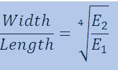
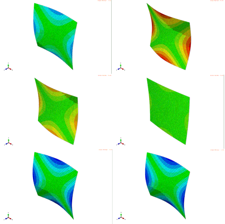
This ratio yields a so-called "Poisson plate". The interesting property of a Freely suspended Poisson plate is that the modal shapes that are associated with the 3 first resonance frequencies are fixed: the first resonance frequency is associated with a torsional modal shape, the second resonance frequency is associated with a saddle modal shape and the third resonance frequency is associated with a breathing modal shape.
So, without the necessity to do an investigation to the nature of the modal shapes, the IET on a Poisson plate reveals the vibrational behaviour of a Poisson plate.
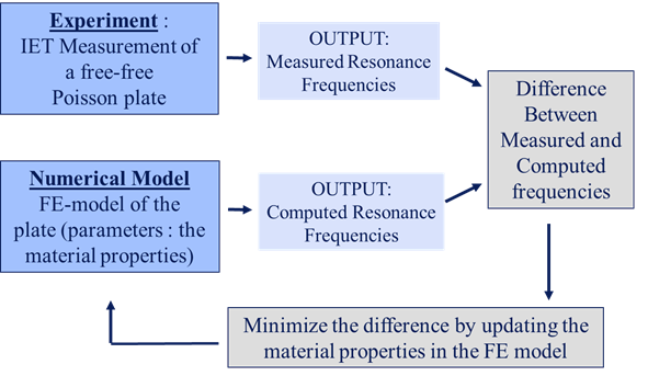
The question is now how to extract the orthotropic Engineering constants from the frequencies measured with IET on the beams and Poisson plate. This problem can be solved by an inverse method (also called" Mixed numerical/experimental method") based on a finite element (FE) computer model of the Poisson plate. A FE model allows computing resonance frequencies for a given set of material properties
In an inverse method, the material properties in the finite element model are updated in such a way that the computed resonance frequencies match the measured resonance frequencies.
Problems with inverse methods are:
· The need of good starting values for the material properties
· Are the parameters converging to the correct physical solution?
· Is the solution unique?
The requirements to obtain good results are:
- · The FE-model must be sufficiently accurate
- · The IET measurements must be sufficiently accurate
- · The starting values must be close enough to the final solution to avoid a local minimum (instead of a global minimum)
- · The computed frequencies in the FE model of the Poisson plate must be sensitive for variations of all the material parameters
In the case the Young's moduli (obtained by IET) are fixed (as non variable parameters) in the inverse method procedure and if only the Poisson's ratio v12 and the in-plane shear modulus G12 are taken as variable parameters in the FE-model, the Resonalyser procedure satisfies all above requirements.
Indeed,
- IET yields very accurate resonance frequencies, even with non-expert equipment,
- a FE of a plate can be made very accurate by selecting a sufficiently fine element grid,
- the knowledge of the modal shapes of a Poisson plate can be used to generate very good starting values using a virtual field method
- and the first 3 natural frequencies of a Poisson plate are sensitive for variations of all the orthotropic Engineering constants.
Standards
- ASTM E1876 - 15 Standard Test Method for Dynamic Youngs Modulus, Shear Modulus, and Poissons Ratio by Impulse Excitation of Vibration. www.astm.org.
- ISO 12680-1:2005 - Methods of test for refractory products -- Part 1: Determination of dynamic Young's modulus (MOE) by impulse excitation of vibration. ISO.
- DIN EN 843-2:2007 Advanced technical ceramics - Mechanical properties of monolithic ceramics at room temperature". webstore.ansi.org.
References
- Roebben, G.; Bollen, B.; Brebels, A.; Van Humbeeck, J.; Van Der Biest, O. (1997-12-01). "Impulse excitation apparatus to measure resonant frequencies, elastic moduli, and internal friction at room and high temperature". Review of Scientific Instruments. 68 (12): 4511–4515. Bibcode:1997RScI...68.4511R. doi:10.1063/1.1148422. ISSN 0034-6748.
- Roebben, G; Basu, B; Vleugels, J; Van Humbeeck, J; Van der Biest, O (2000-09-28). "The innovative impulse excitation technique for high-temperature mechanical spectroscopy". Journal of Alloys and Compounds. Intern. Conf. Internal Friction and Ultrasonic Attentuation in Solids (ICIFUAS-12). 310 (1–2): 284–287. doi:10.1016/S0925-8388(00)00966-X.
- Massara, Nazareno; Boccaleri, Enrico; Milanesio, Marco; Lopresti, Mattia (1 October 2021). "IETeasy: An open source and low-cost instrument for impulse excitation technique, applied to materials classification by acoustical and mechanical properties assessment". HardwareX. 10: e00231. doi:10.1016/j.ohx.2021.e00231. PMC 9123443. PMID 35607698.
- Jung, Il-Chan; Kang, Deok-Gu; Cooman, Bruno C. De (2013-11-26). "Impulse Excitation Internal Friction Study of Dislocation and Point Defect Interactions in Ultra-Low Carbon Bake-Hardenable Steel". Metallurgical and Materials Transactions A. 45 (4): 1962–1978. doi:10.1007/s11661-013-2122-z. ISSN 1073-5623. S2CID 136855858.
- Germany, GHI/RWTH-Aachen, Aachen, Germany, Institute of Mineral Engineering – Department of Ceramics and Refractory Materials, Aachen (2015-01-01). "Estimation of Damage in Refractory Materials after Progressive Thermal Shocks with Resonant Frequency Damping Analysis". Journal of Ceramic Science and Technology. 7 (2). doi:10.4416/jcst2015-00080.
{{cite journal}}: CS1 maint: multiple names: authors list (link) - Massara, Nazareno; Boccaleri, Enrico; Milanesio, Marco; Lopresti, Mattia (1 October 2021). "IETeasy: An open source and low-cost instrument for impulse excitation technique, applied to materials classification by acoustical and mechanical properties assessment". HardwareX. 10: e00231. doi:10.1016/j.ohx.2021.e00231. PMC 9123443. PMID 35607698.
- Non-destructive testing : proceedings of the First Joint Belgian-Hellenic Conference on Non-Destructive Testing, Patras, Greece, 22-23 May 1995. Hemelrijck, Danny van., Anastassopoulos, Athanassios. Rotterdam: A.A. Balkema. 1996. ISBN 90-5410-595-X. OCLC 35306088.
{{cite book}}: CS1 maint: others (link) - "Theoretical Background of the Resonalyser Procedure".
- T. Lauwagie, H. Sol, G. Roebben, W. Heylen and Y. Shi (2002). "Validation_of_the_Resonalyser_method_an_inverse_method_for_material_identification".
{{cite web}}: CS1 maint: multiple names: authors list (link) - Lauwagie, Tom; Sol, Hugo; Roebben, Gert; Heylen, Ward; Shi, Yinming; Van der Biest, Omer (2003-10-01). "Mixed numerical–experimental identification of elastic properties of orthotropic metal plates". NDT & E International. 36 (7): 487–495. doi:10.1016/S0963-8695(03)00048-3. ISSN 0963-8695.
- Sol, H. (1997). Material Identification Using Mixed Numerical Experimental Methods : Proceedings of the EUROMECH Colloquium held in Kerkrade, the Netherlands, 7-9 April 1997. Oomens, C. W. J. Dordrecht: Springer Netherlands. ISBN 978-94-009-1471-1. OCLC 851370715.


 with W the energy of the system