Unpolarized light is light with a random, time-varying polarization. Natural light, like most other common sources of visible light, is produced independently by a large number of atoms or molecules whose emissions are uncorrelated.
Unpolarized light can be produced from the incoherent combination of vertical and horizontal linearly polarized light, or right- and left-handed circularly polarized light. Conversely, the two constituent linearly polarized states of unpolarized light cannot form an interference pattern, even if rotated into alignment (Fresnel–Arago 3rd law).
A so-called depolarizer acts on a polarized beam to create one in which the polarization varies so rapidly across the beam that it may be ignored in the intended applications. Conversely, a polarizer acts on an unpolarized beam or arbitrarily polarized beam to create one which is polarized.
Unpolarized light can be described as a mixture of two independent oppositely polarized streams, each with half the intensity. Light is said to be partially polarized when there is more power in one of these streams than the other. At any particular wavelength, partially polarized light can be statistically described as the superposition of a completely unpolarized component and a completely polarized one. One may then describe the light in terms of the degree of polarization and the parameters of the polarized component. That polarized component can be described in terms of a Jones vector or polarization ellipse. However, in order to also describe the degree of polarization, one normally employs Stokes parameters to specify a state of partial polarization.
Motivation
The transmission of plane waves through a homogeneous medium are fully described in terms of Jones vectors and 2×2 Jones matrices. However, in practice there are cases in which all of the light cannot be viewed in such a simple manner due to spatial inhomogeneities or the presence of mutually incoherent waves. So-called depolarization, for instance, cannot be described using Jones matrices. For these cases it is usual instead to use a 4×4 matrix that acts upon the Stokes 4-vector. Such matrices were first used by Paul Soleillet in 1929, although they have come to be known as Mueller matrices. While every Jones matrix has a Mueller matrix, the reverse is not true. Mueller matrices are then used to describe the observed polarization effects of the scattering of waves from complex surfaces or ensembles of particles, as shall now be presented.
Coherency matrix
The Jones vector perfectly describes the state of polarization and phase of a single monochromatic wave, representing a pure state of polarization as described above. However any mixture of waves of different polarizations (or even of different frequencies) do not correspond to a Jones vector. In so-called partially polarized radiation the fields are stochastic, and the variations and correlations between components of the electric field can only be described statistically. One such representation is the coherency matrix:
where angular brackets denote averaging over many wave cycles. Several variants of the coherency matrix have been proposed: the Wiener coherency matrix and the spectral coherency matrix of Richard Barakat measure the coherence of a spectral decomposition of the signal, while the Wolf coherency matrix averages over all time/frequencies.
The coherency matrix contains all second order statistical information about the polarization. This matrix can be decomposed into the sum of two idempotent matrices, corresponding to the eigenvectors of the coherency matrix, each representing a polarization state that is orthogonal to the other. An alternative decomposition is into completely polarized (zero determinant) and unpolarized (scaled identity matrix) components. In either case, the operation of summing the components corresponds to the incoherent superposition of waves from the two components. The latter case gives rise to the concept of the "degree of polarization"; i.e., the fraction of the total intensity contributed by the completely polarized component.
Stokes parameters
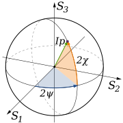
Main article: Stokes parametersThe coherency matrix is not easy to visualize, and it is therefore common to describe incoherent or partially polarized radiation in terms of its total intensity (I), (fractional) degree of polarization (p), and the shape parameters of the polarization ellipse. An alternative and mathematically convenient description is given by the Stokes parameters, introduced by George Gabriel Stokes in 1852. The relationship of the Stokes parameters to intensity and polarization ellipse parameters is shown in the equations and figure below.
Here Ip, 2ψ and 2χ are the spherical coordinates of the polarization state in the three-dimensional space of the last three Stokes parameters. Note the factors of two before ψ and χ corresponding respectively to the facts that any polarization ellipse is indistinguishable from one rotated by 180°, or one with the semi-axis lengths swapped accompanied by a 90° rotation. The Stokes parameters are sometimes denoted I, Q, U and V.
The four Stokes parameters are enough to describe 2D polarization of a paraxial wave, but not the 3D polarization of a general non-paraxial wave or an evanescent field.
Poincaré sphere
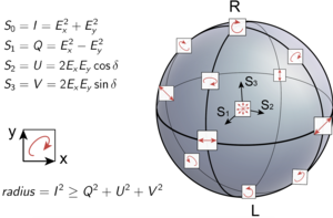
Neglecting the first Stokes parameter S0 (or I), the three other Stokes parameters can be plotted directly in three-dimensional Cartesian coordinates. For a given power in the polarized component given by
the set of all polarization states are then mapped to points on the surface of the so-called Poincaré sphere (but of radius P), as shown in the accompanying diagram. In quantum mechanics and computing, a related concept is the Bloch sphere.


Often the total beam power is not of interest, in which case a normalized Stokes vector is used by dividing the Stokes vector by the total intensity S0:
The normalized Stokes vector then has unity power () and the three significant Stokes parameters plotted in three dimensions will lie on the unity-radius Poincaré sphere for pure polarization states (where ). Partially polarized states will lie inside the Poincaré sphere at a distance of from the origin. When the non-polarized component is not of interest, the Stokes vector can be further normalized to obtain
When plotted, that point will lie on the surface of the unity-radius Poincaré sphere and indicate the state of polarization of the polarized component.
Any two antipodal points on the Poincaré sphere refer to orthogonal polarization states. The overlap between any two polarization states is dependent solely on the distance between their locations along the sphere. This property, which can only be true when pure polarization states are mapped onto a sphere, is the motivation for the invention of the Poincaré sphere and the use of Stokes parameters, which are thus plotted on (or beneath) it.
See also
References
- Chipman, R.A.; Lam, W.S.T.; Young, G. (2018). Polarized Light and Optical Systems. Optical Sciences and Applications of Light. CRC Press. ISBN 978-1-4987-0057-3. Retrieved 2023-01-20.
- Sharma, K.K. (2006). Optics: Principles and Applications. Elsevier Science. p. 145. ISBN 978-0-08-046391-9. Retrieved 2023-01-20.
- Prakash, Hari; Chandra, Naresh (1971). "Density Operator of Unpolarized Radiation". Physical Review A. 4 (2): 796–799. Bibcode:1971PhRvA...4..796P. doi:10.1103/PhysRevA.4.796.
- Chandrasekhar, Subrahmanyan (2013). Radiative transfer. Courier. p. 30.
- ^ Hecht, Eugene (2002). Optics (4th ed.). United States of America: Addison Wesley. ISBN 0-8053-8566-5.
- Bekefi, George; Barrett, Alan (1977). Electromagnetic Vibrations, Waves, and Radiation. USA: MIT Press. ISBN 0-262-52047-8.
- Edward L. O'Neill (January 2004). Introduction to Statistical Optics. Courier Dover Publications. ISBN 978-0-486-43578-7.
- Eismann, J. S.; Nicholls, L. H.; Roth, D. J.; Alonso, M. A.; Banzer, P.; Rodríguez-Fortuño, F. J.; Zayats, A. V.; Nori, F.; Bliokh, K. Y. (2021). "Transverse spinning of unpolarized light". Nature Photonics. 15 (2): 156–161. arXiv:2004.02970. Bibcode:2021NaPho..15..156E. doi:10.1038/s41566-020-00733-3. ISSN 1749-4885. S2CID 215238513.
- Sugic, Danica; Dennis, Mark R.; Nori, Franco; Bliokh, Konstantin Y. (2020-12-23). "Knotted polarizations and spin in three-dimensional polychromatic waves". Physical Review Research. 2 (4): 042045. arXiv:2007.13307. Bibcode:2020PhRvR...2d2045S. doi:10.1103/PhysRevResearch.2.042045. ISSN 2643-1564.


 then has unity power (
 ) and the three significant Stokes parameters plotted in three dimensions will lie on the
  ). Partially polarized states will lie inside the Poincaré sphere at a distance of
  from the origin. When the non-polarized component is not of interest, the Stokes vector can be further normalized to obtain
