| This article relies largely or entirely on a single source. Relevant discussion may be found on the talk page. Please help improve this article by introducing citations to additional sources. Find sources: "Thyristor-controlled reactor" – news · newspapers · books · scholar · JSTOR (March 2015) |
In an electric power transmission system, a thyristor-controlled reactor (TCR) is a reactance connected in series with a bidirectional thyristor valve. The thyristor valve is phase-controlled, which allows the value of delivered reactive power to be adjusted to meet varying system conditions. Thyristor-controlled reactors can be used for limiting voltage rises on lightly loaded transmission lines. Another device which used to be used for this purpose is a magnetically controlled reactor (MCR), a type of magnetic amplifier otherwise known as a transductor.
In parallel with series connected reactance and thyristor valve, there may also be a capacitor bank, which may be permanently connected or which may use mechanical or thyristor switching. The combination is called a static VAR compensator.
Circuit diagram
A thyristor controlled reactor is usually a three-phase assembly, normally connected in a delta arrangement to provide partial cancellation of harmonics. Often the main TCR reactor is split into two halves, with the thyristor valve connected between the two halves. This protects the vulnerable thyristor valve from damage due to flashovers, lightning strikes etc.
Operating principles
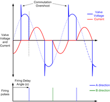
The current in the TCR is varied from maximum (determined by the connection voltage and the inductance of the reactor) to almost zero by varying the "Firing Delay Angle", α. α is defined as the delay angle from the point at which the voltage becomes positive to the point at which the thyristor valve is turned on and current starts to flow.

Maximum current is obtained when α is 90°, at which point the TCR is said to be in "full conduction" and the rms current is given by:
Where:
Vsvc is the rms value of the line-to-line busbar voltage to which the SVC is connected
Ltcr is the total TCR inductance per phase
The current lags 90° behind the voltage in accordance with classical AC circuit theory. As α increases above 90°, up to a maximum of 180°, the current decreases and becomes discontinuous and non-sinusoidal. The TCR current, as a function of time, is then given by:
Otherwise, zero.
Main equipment
A TCR comprises two main items of equipment: the reactor itself, which is usually air-cored (although iron-cored reactors are possible) and the thyristor valve. Depending on the system voltage, an intermediate power transformer may be required to step up from the voltage handled by the thyristors to the transmission system voltage.
Thyristor valve
The thyristor valve typically consists of 5-20 inverse-parallel-connected pairs of thyristors connected in series. The inverse-parallel connection is needed because most commercially available thyristors can conduct current in only one direction. The series connection is needed because the maximum voltage rating of commercially available thyristors (up to approximately 8.5 kV) is insufficient for the voltage at which the TCR is connected. For some low-voltage applications, it may be possible to avoid the series-connection of thyristors; in such cases the thyristor valve is simply an inverse-parallel connection of two thyristors.


In addition to the thyristors themselves, each inverse-parallel pair of thyristors has a resistor - capacitor circuit connected across it, to force the voltage across the valve to divide uniformly amongst the thyristors and to damp the "commutation overshoot" which occurs when the valve turns off.
Harmonics
A TCR operating with α > 90° generates substantial amounts of harmonic currents, particularly at 3rd, 5th and 7th harmonics. By connecting the TCR in delta, the harmonic currents of order 3n ("triplen harmonics") flow only around the delta and do not escape into the connected AC system. However, the 5th and 7th harmonics (and to a lesser extent 11th, 13th, 17th etc.) must be filtered in order to prevent excessive voltage distortion on the AC network. This is usually accomplished by connecting harmonic filters in parallel with the TCR. The filters provide capacitive reactive power which partly offsets the inductive reactive power provided by the TCR.
References
- "Thyristor Controlled Reactor: Circuit Diagram | PDF | Electrical Engineering | Electromagnetism". Scribd. Retrieved 2024-08-20.


