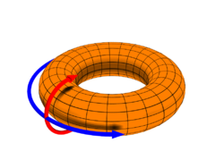
The terms toroidal and poloidal refer to directions relative to a torus of reference. They describe a three-dimensional coordinate system in which the poloidal direction follows a small circular ring around the surface, while the toroidal direction follows a large circular ring around the torus, encircling the central void.
The earliest use of these terms cited by the Oxford English Dictionary is by Walter M. Elsasser (1946) in the context of the generation of the Earth's magnetic field by currents in the core, with "toroidal" being parallel to lines of constant latitude and "poloidal" being in the direction of the magnetic field (i.e. towards the poles).
The OED also records the later usage of these terms in the context of toroidally confined plasmas, as encountered in magnetic confinement fusion. In the plasma context, the toroidal direction is the long way around the torus, the corresponding coordinate being denoted by z in the slab approximation or ζ or φ in magnetic coordinates; the poloidal direction is the short way around the torus, the corresponding coordinate being denoted by y in the slab approximation or θ in magnetic coordinates. (The third direction, normal to the magnetic surfaces, is often called the "radial direction", denoted by x in the slab approximation and variously ψ, χ, r, ρ, or s in magnetic coordinates.)
Example
As a simple example from the physics of magnetically confined plasmas, consider an axisymmetric system with circular, concentric magnetic flux surfaces of radius (a crude approximation to the magnetic field geometry in an early tokamak but topologically equivalent to any toroidal magnetic confinement system with nested flux surfaces) and denote the toroidal angle by and the poloidal angle by . Then the toroidal/poloidal coordinate system relates to standard Cartesian coordinates by these transformation rules:
where .
The natural choice geometrically is to take , giving the toroidal and poloidal directions shown by the arrows in the figure above, but this makes a left-handed curvilinear coordinate system. As it is usually assumed in setting up flux coordinates for describing magnetically confined plasmas that the set forms a right-handed coordinate system, , we must either reverse the poloidal direction by taking , or reverse the toroidal direction by taking . Both choices are used in the literature.
Kinematics
To study single particle motion in toroidally confined plasma devices, velocity and acceleration vectors must be known. Considering the natural choice , the unit vectors of toroidal and poloidal coordinates system can be expressed as:
according to Cartesian coordinates. The position vector is expressed as:
The velocity vector is then given by:
and the acceleration vector is:
See also
References
- "Oxford English Dictionary Online". poloidal. Oxford University Press. Retrieved 2007-08-10.
- Elsasser, W. M. (1946). "Induction Effects in Terrestrial Magnetism, Part I. Theory". Phys. Rev. 69 (3–4): 106–116. doi:10.1103/PhysRev.69.106. Retrieved 2007-08-10.
 (a crude approximation to the magnetic field geometry in an early
  and the poloidal angle by
  .
Then the toroidal/poloidal coordinate system relates to standard


 .
.
 , giving the toroidal and poloidal directions shown by the arrows in the figure above, but this makes
  a left-handed curvilinear coordinate system. As it is usually assumed in setting up
  , we must either reverse the poloidal direction by taking
  , or reverse the toroidal direction by taking
  . Both choices are used in the literature.
 can be expressed as:


