| This article needs additional citations for verification. Please help improve this article by adding citations to reliable sources. Unsourced material may be challenged and removed. Find sources: "Variable-geometry turbocharger" – news · newspapers · books · scholar · JSTOR (July 2018) (Learn how and when to remove this message) |

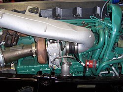
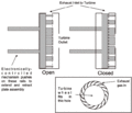
Variable-geometry turbochargers (VGTs), occasionally known as variable-nozzle turbochargers (VNTs), are a type of turbochargers, usually designed to allow the effective aspect ratio (A/R ratio) of the turbocharger to be altered as conditions change. This is done with the use of adjustable vanes located inside the turbine housing between the inlet and turbine, these vanes affect flow of gases towards the turbine. The benefit of the VGT is that the optimum aspect ratio at low engine speeds is very different from that at high engine speeds.
If the aspect ratio is too large, the turbo will fail to create boost at low speeds; if the aspect ratio is too small, the turbo will choke the engine at high speeds, leading to high exhaust manifold pressures, high pumping losses, and ultimately lower power output. By altering the geometry of the turbine housing as the engine accelerates, the turbo's aspect ratio can be maintained at its optimum. Because of this, VGTs have a minimal amount of lag, a low boost threshold, and high efficiency at higher engine speeds.
-
A cut open VGT turbocharger (VW Golf, Diesel)
-
 Exhaust side with variable-geometry guide vanes
-
charge air side with compressor wheel
-
Turbo shaft bearings
-
Turbo shaft bearings
History
The rotating-vane VGT was first developed under Garrett and patented in 1953.
One of the first production cars to use these turbochargers was the 1988 Honda Legend; it used a water-cooled VGT installed on its 2.0-litre V6 engine.
The limited-production 1989 Shelby CSX-VNT, with only 500 examples produced, was equipped with a 2.2-litre Chrysler K engine with a Garrett turbo called the VNT-25 (because it used the same compressor and shaft as the fixed-geometry Garrett T-25).
In 1991, Fiat incorporated a VGT into the Croma's direct-injected turbodiesel.
The Peugeot 405 T16, launched in 1992, used a Garrett VAT25 variable-geometry turbocharger on its 2.0-litre 16-valve engine.
The 2007 Porsche 911 Turbo has twin variable-geometry turbochargers on its 3.6-litre horizontally-opposed six-cylinder gasoline engine.
In 2007, Acura introduced the RDX with Variable Geometry Turbocharger following a (VFT) design.
The 2015 Koenigsegg One:1 uses twin variable-geometry turbochargers on its 5.0-litre V8 engine, allowing it to produce 1361 horsepower.
Common designs
The most common implementations of VGTs are Variable-Nozzle Turbines (VNT), Sliding Wall Turbines, and Variable Flow Turbines (VFT).
Variable-Nozzle Turbines are common in light-duty engines (passenger cars, race cars, and light commercial vehicles). The turbine's vanes rotate in unison, relative to its hub, to vary its pitch and cross-sectional area. VNTs offer higher flow rates and higher peak efficiency compared to other variable geometry designs.
Sliding Wall Turbines are commonly found in heavy-duty engines. The vanes do not rotate, but instead, their effective width is changed. This is usually done by moving the turbine along its axis, partially retracting the vanes within the housing. Alternatively, a partition within the housing may slide back and forth. The area between the edges of the vanes changes, leading to a variable-aspect-ratio system with fewer moving parts.
Variable Flow Turbines are another simplified version of a VGT when compared to a VNT. This design uses a two-volute turbine housing with a blend gate located in the neck. The gate can vary the flow between the scrolls to average the optimal A/R ratio. In low flow conditions exhaust gas is routed through the primary volute and under peak flow it is directed through both the primary and secondary. This design has a lower flow rate compared to VNT types so a wastegate may be incorporated with this design.
VGTs may be controlled by a membrane vacuum actuator, electric servo, 3-phase electric actuation, hydraulic actuator, or pneumatic actuator using air brake pressure.
Unlike fixed-geometry turbines, VGTs do not require a wastegate. Although VGTs do not require a wastegate, some applications requiring a high mass air flow ratio will benefit from an additional wastegate most commonly found in high performance spark ignition engines. This is in contrast to diesel engines.
Use
VGTs tend to be much more common on diesel engines, as lower exhaust temperatures mean they are less prone to failure. Early gasoline-engine VGTs required significant pre-charge cooling to extend the turbocharger life to reasonable levels, but advances in technology have improved their resistance to high-temperature gasoline exhaust, and they have started to appear increasingly in gasoline-engine cars.
Typically, VGTs are only found in OEM applications due to the level of coordination required to keep the vanes in the most optimal position for whatever state the engine is in. However, there are aftermarket VGT control units available, and some high-end aftermarket engine management systems can control VGTs as well.
In trucks, VGTs are also used to control the ratio of exhaust recirculated back to the engine inlet (they can be controlled to selectively increase the exhaust manifold pressure until it exceeds the inlet manifold pressure, which promotes exhaust gas recirculation). Although excessive engine backpressure is detrimental to overall fuel efficiency, ensuring a sufficient EGR rate even during transient events (such as gear changes) can be sufficient to reduce nitrogen oxide emissions down to that required by emissions legislation (e.g., Euro 5 for Europe and EPA 10 for the USA).
Another use for sliding-vane turbochargers is as a downstream exhaust brake, so that an extra exhaust throttle valve is not needed. The mechanism can also be deliberately modified to reduce the turbine efficiency in a pre-defined position. This mode can be selected to sustain a raised exhaust temperature to promote "light-off" and "regeneration" of a diesel particulate filter (this involves heating the carbon particles stuck in the filter until they oxidize away in a semi-self-sustaining reaction - rather like the self-cleaning process some ovens offer). Actuation of a VGT for EGR flow control, or to implement braking or regeneration modes in general, requires hydraulic actuators or electric servos.
VGTs offer improved transient response over conventional fixed geometry turbochargers. This makes VGTs ideal for use in vehicles where power demand is very dynamic. In situations where engine load is constant like in stationary generators, fixed geometry turbochargers can provide higher efficiency over VGTs. This is due to the added exhaust resistance created from the tolerances of the moving parts within a VGT.
Manufacturers
Several companies manufacture and supply rotating-vane variable-geometry turbochargers, including Garrett, BorgWarner, and Mitsubishi Heavy Industries. This design is mostly limited to small engines and light-duty applications (passenger cars, race cars and light commercial vehicles).
The main supplier of sliding-vane VGTs is Holset Engineering.
References
- ^ , "Turbosupercharger", issued 1953-06-08
- "Turbo Pioneer". honeywell.com. Archived from the original on 2012-05-04. Retrieved 2014-01-22.
- Tang, Huayin; Pennycott, Andrew; Akehurst, Sam; Brace, Chris J (2014-10-06). "A review of the application of variable geometry turbines to the downsized gasoline engine". International Journal of Engine Research. 16 (6): 810–825. doi:10.1177/1468087414552289. ISSN 1468-0874.
- Khac, Hoang Nguyen (2017-11-20). "Design of diesel engine's optimal control maps for high efficiency and emission reduction". S2CID 67274667.
{{cite journal}}: Cite journal requires|journal=(help) - Ishihara, Hiromitsu; Adachi, Kazunari; Kono, Shinji (2002-07-09). "Development of VFT Part 2". SAE Technical Paper Series. Vol. 1. doi:10.4271/2002-01-2165.
- Halderman, James D. (2012). Fuel and Emissions Control Systems (3rd ed.). Prentice Hall. p. 69. ISBN 978-0-13-254292-0.
- ^ "My Holset Turbo | Variable Geometry Turbos". www.myholsetturbo.com. Retrieved 2020-02-03.
- Gabriel, Holger; Jacob, Stefan; Münkel, Uwe; Rodenhäuser, Helmut; Schmalzl, Hans-Peter (February 2007). "The turbocharger with variable turbine geometry for gasoline engines". MTZ Worldwide. 68 (2): 7–10. doi:10.1007/bf03226804. ISSN 2192-9114.
External links
- How does Variable Turbine Geometry Work?
- Variable Turbine Geometry (VTG) explanation with pictures
- Cummins Turbochargers & Air Handling
| Internal combustion engine | |
|---|---|
| Part of the Automobile series | |
| Engine block and rotating assembly | |
| Valvetrain and Cylinder head | |
| Forced induction | |
| Fuel system | |
| Ignition | |
| Engine management | |
| Electrical system | |
| Intake system | |
| Exhaust system | |
| Cooling system | |
| Lubrication | |
| Other | |

