This article has multiple issues. Please help improve it or discuss these issues on the talk page. (Learn how and when to remove these messages)
|


In electric power, a bushing is a hollow electrical insulator that allows an electrical conductor to pass safely through a conducting barrier such as the case of a transformer or circuit breaker without making electrical contact with it. Bushings are typically made from porcelain, though other insulating materials are also used.
Explanation
All materials carrying an electric charge generate an electric field. When an energized conductor is near a material at earth potential, it can form very high field strengths, especially where the field lines are forced to curve sharply around the earthed material. The bushing controls the shape and strength of the field and reduces the electrical stresses in the insulating material.
Bushing condenser
A bushing must be designed to withstand the electrical field strength produced in the insulation, when any earthed material is present. As the strength of the electrical field increases, leakage paths may develop within the insulation. If the energy of the leakage path overcomes the dielectric strength of the insulation, it may puncture the insulation and allow the electrical energy to conduct to the nearest earthed material causing burning and arcing.
A typical bushing design has a conductor, usually of copper or aluminium, occasionally of other conductive material, surrounded by insulation, except for the terminal ends.
In the case of a busbar, the conductor terminals will support the busbar in its location. In the case of a bushing, a fixing device will also be attached to the insulation to hold it in its location. Usually, the fixing point is integral or surrounds the insulation over part of the insulated surface. The insulated material between the fixing point and the conductor is the most highly stressed area.
The design of any electrical bushing must ensure that the electrical strength of the insulated material is able to withstand the penetrating 'electrical energy' passing through the conductor, via any highly stressed areas. It must also be capable of enduring, occasional and exceptional high voltage moments as well as the normal continual service withstand voltage, as it is the voltage that directs and controls the development of leakage paths and not current.
Insulated bushings can be installed either indoor, or outdoor, and the selection of insulation will be determined by the location of the installation and the electrical service duty on the bushing.
For a bushing to work successfully over many years, the insulation must remain effective both in composition and design shape and will be key factors in its survival. Bushings can therefore vary considerably in both material and design style.
Types
Porcelain insulation
The earliest bushing designs use porcelain for both indoor and outdoor applications. Porcelain was originally used due to its properties of being impervious to moisture once sealed by fired glaze, and low manufacturing cost. The main disadvantage with porcelain is that its small value of linear expansion has to be accommodated by using flexible seals and substantial metal fittings, both of which present manufacturing and operational problems.
A basic porcelain bushing is a hollow porcelain shape that fits through a hole in a wall or metal case, allowing a conductor to pass through its center, and connect at both ends to other equipment. Bushings of this type are often made of wet-process fired porcelain, which is then glazed. A semi-conducting glaze may be used to assist in equalizing the electrical potential gradient along the length of the bushing.
The inside of the porcelain bushing is often filled with oil to provide additional insulation and bushings of this construction are widely used up to 36 kV where higher partial discharges are permitted.
Where partial discharge is required to conform to IEC 60137, paper and resin insulated conductors are used in conjunction with porcelain, for unheated indoor and outdoor applications.
The use of resin (polymer, polymeric, composite) insulated bushings for high voltage applications is common, although most high-voltage bushings are usually made of resin impregnated paper insulation around the conductor with porcelain or polymer weather sheds, for the outdoor end and occasionally for the indoor end.
Paper insulation
Another early form of insulation was paper, however, paper is hygroscopic and absorbs moisture which is detrimental and is disadvantaged by the inflexible linear designs. Cast resin technology has dominated insulated products since the 1960s, due to its flexibility of shape and its higher dielectrical strength.
Typically, paper insulation is later impregnated either with oil (historically), or more commonly today with resin. In the case of resin, the paper is film coated with a phenolic resin to become synthetic resin bonded paper (SRBP), or impregnated after dry winding with epoxy resins, to become resin impregnated paper or epoxy resin impregnated paper (RIP, ERIP).
SRBP insulated bushings are typically used up to voltages around 72.5 kV. However, above 12 kV, there is a need to control the external electrical field and to even out the internal energy storage which marginalises the dielectric strength of paper insulation.
To improve the performance of paper insulated bushings, metallic foils can be inserted during the winding process. These act to stabilize the generated electrical fields, homogenising the internal energy using the effect of capacitance. This feature resulted in the condenser/capacitor bushing.
The condenser bushing is made by inserting very fine layers of metallic foil into the paper during the winding process. The inserted conductive foils produce a capacitive effect which dissipates the electrical energy more evenly throughout the insulated paper and reduces the electric field stress between the energised conductor and any earthed material.
Condenser bushings produce electric stress fields which are significantly less potent around the fixing flange than designs without foils and, when used in conjunction with resin impregnation, produce bushings which can be used at service voltages over one million volts with great success.
Resin insulation
Since the 1965s, resin materials have been used for all types of bushing up to the highest voltages. The flexibility of using a castable form of insulation has replaced paper insulation in many product areas and dominates the existing insulated bushing market.
As with paper insulation, the control of electric stress fields remains important. Resin insulation has greater dielectric strength than paper and requires less stress control at voltages below 25 kV. However, some compact and higher rated switchgear designs, have earthed materials closer to bushings than in the past and these designs may require stress control screens in resin bushings operating as low as 12 kV Fixing points are often integral with the main resin form, and present fewer problems to earthed materials than the metal flanges used on paper bushings.
However, care must be observed in resin insulated bushings designs which use internally cast screens such that the benefit of electrical stress field control is not off set by increasing partial discharge caused by the difficulties of eliminating micro voids in the resin around the screens during the casting process. The need to eliminate voids in resin becomes more sensitive as voltages increases, and it is normal to revert to resin impregnated, foiled paper insulation for bushings rated over 72.5 kV.
-
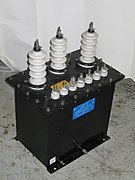
 Bushings on small ferroresonant transformer
-
 Bushings on single phase distribution transformer
-
 20 kV bushings on transformers and cables
-
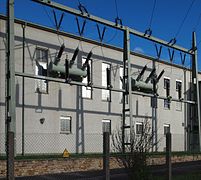
 110 kV bushings in a building wall
-
 Bushings for 110 kV and 220 kV
-
 Bushings on 380 kV transformer and GIS connection
-
 Bushing on 1 MV AEG utility transformer, Germany, 1932
Bushing failure
 Dry bushing
 Oil filled capacitor bushing
 Oil filled capacitor bushing
Bushings sometimes fail due to partial discharge. This is sometimes due to the slow and progressive degradation of the insulation over many years of energized service; however, it may also be a rapid degeneration which destroys a good bushing in a matter of hours. At present, there is great interest by the electricity supply industry in monitoring the condition of high-voltage bushings. However, some bushings failing early in service are due to failures to control voltage or carry out essential maintenance, while others relate to incipient failure mechanisms built in at manufacture. This view is evidenced by the minority of bushing failures worldwide.
Electrical and Structural Analysis
A Finite element method analysis is usually performed before qualifying a bushing for use in a new equipment/location. This is specially true of bushings around high-voltage conductors. The electrical analysis usually focusses on the creation of the electric field around the conductor and how the shape of the bushing effects that field. The structural analysis considers the loads (wind, snow, earthquakes, rain, etc.) that the bushing is expected to survive.
References
- Central Electricity Generating Board (1982). Modern Power Station Practice. Pergamon. ISBN 0-08-016436-6.
- IEC 60137:2008, BEAIRA Technical Report Q/T123-1952 Design of High Voltage Stress Controlled Condenser-Type Bushings and Capacitors, BEAIRA Technical Report Q/T125-1952 Stresses in High Voltage Condenser Bushings, BS EN 50180, 50181, 50386
