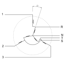

An induction regulator is an alternating current electrical machine, somewhat similar to an induction motor, which can provide a continuously variable output voltage. The induction regulator was an early device used to control the voltage of electric networks. Since the 1930s it has been replaced in distribution network applications by the tap transformer. Its usage is now mostly confined to electrical laboratories, electrochemical processes and arc welding. With minor variations, its setup can be used as a phase-shifting power transformer.
Construction
A single-phase induction regulator has a (primary) excitation winding, connected to the supply voltage, wound on a magnetic core which can be rotated. The stationary secondary winding is connected in series with the circuit to be regulated. As the excitation winding is rotated through 180 degrees, the voltage induced in the series winding changes from adding to the supply voltage to opposing it. By selection of the ratios of the number of turns on the excitation and series windings, the range of voltage can be adjusted, say, plus or minus 20% of the supply voltage, for example.
The three phase induction regulator can be regarded as a wound induction motor. The rotor is not allowed to turn freely and it can be mechanically shifted by means of a worm gear. The rest of the regulator's construction follows that of a wound rotor induction motor with a slotted three-phase stator and a wound three-phase rotor. Since the rotor is not allowed to turn more than 180 degrees, mechanically, the rotor leads can be connected by flexible cables to the exterior circuit. If the stator winding is a two-pole winding, moving the rotor through 180 degrees physically will change the phase of the induced voltage by 180 degrees. A four-pole winding only requires 90 degrees of physical movement to produce 180 degrees of phase shift.
Since a torque is produced by the interaction of the magnetic fields, the movable element is held by a mechanism such as a worm gear. The rotor may be rotated by a hand wheel attached to the machine, or an electric motor can be used to remotely or automatically adjust the rotor position.
Depending on the application, the ratio of number of turns on the rotor and the stator can vary.
Working
Since the single phase regulator only changes the flux linking the excitation and series windings, it does not introduce a phase shift between the supply voltage and the load voltage. However, the varying position of the movable element in the three-phase regulator does create a phase shift. This may be a concern if the load circuit may be connected to more than one supply, since circulating currents will flow owing to the phase shift.
If the rotor terminals are connected to a three-phase electric power network, a rotating magnetic field will be driven into the magnetic core. The resulting flux will produce an emf on the windings of the stator with the particularity that if rotor and stator are physically shifted by an angle α, then the electric phase shifting of both windings is α too. Considering just the fundamental harmonic, and ignoring the shifting, the following equation rules:
Where ξ is the winding factor, a constant related to the construction of the windings.
If the stator winding is connected to the primary phase, the total voltage seen from the neutral (N) will be the sum of the voltages at both windings rotor and stator. Translating this to electric phasors, both phasors are connected. There is an angular shifting of α between them. Since α can be freely chosen between , both phasors can be added or subtracted, so all the values in between are attainable. The primary and secondary are not isolated. Also, the ratio of the magnitudes of voltages between rotor and stator is constant; the resultant voltage varies owing to the angular shifting of the series winding induced voltage.
Advantages
The output voltage can be continuously regulated within the nominal range. This is a clear benefit against tap transformers where output voltage takes discrete values. Also, the voltage can be easily regulated under working conditions.
Drawbacks
In comparison to tap transformers, induction regulators are expensive, with lower efficiency, high open circuit currents (due to the airgap) and limited in voltage to less than 20kV.
Applications
An induction regulator for power networks is usually designed to have a nominal voltage of 14kV and ±(10-15)% of regulation, but this use has declined. Nowadays, its main uses are in electrical laboratories and arc welding.
See also
Bibliography
- Arnold, Archibald (1946). The Modern Electrical Engineer, Volume II, Fourth Edition. The Caxton Publishing Company, Limited. pp. 163–166.
- Houston, Edwin J. (1902). Recent Types of Dynamo-Electric Machinery. P. F. Collier and Son. pp. 564–567.
- Fink, Donald G. (1978). Standard Handbook for Electrical Engineers, Eleventh Edition. McGraw-Hill. pp. 10.94–10.95. ISBN 0-07-020974-X.

