| This article needs additional citations for verification. Please help improve this article by adding citations to reliable sources. Unsourced material may be challenged and removed. Find sources: "Rotary transformer" – news · newspapers · books · scholar · JSTOR (December 2009) (Learn how and when to remove this message) |


- Left: The fixed portion of a 6 channel rotary transformer used in a six-head VCR. Two additional shorted turns improve the isolation of the two outermost windings from each other and from the other, innermost windings.
- Right: The rotating portion of the rotary transformer showing three of the six tape heads


A rotary (rotatory) transformer is a specialized transformer used to couple electrical signals between two parts that rotate in relation to each other. They may be either cylindrical or 'pancake' shaped.
Slip rings can be used for the same purpose, but are subject to friction, wear, intermittent contact, and limitations on the rotational speed that can be accommodated without damage. Wear can be eliminated by using a pool of liquid mercury or liquid metal alloy instead of a solid ring contact, but the toxicity and slow corrosion of mercury are problematic, and very high rotational speeds are again difficult to achieve. A rotary transformer has none of these limitations.
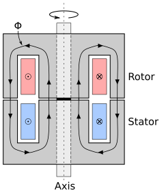
Rotary transformers are constructed by winding the primary and secondary windings into separate halves of a cup core; these concentric halves face each other, with each half mounted to one of the rotating parts. Magnetic flux provides the coupling from one half of the cup core to the other across an air gap, providing the mutual inductance that couples energy from the transformer's primary to its secondary.
In brushless synchros, typical rotary transformers (in pairs) provide longer life than slip rings. These rotary transformers have a cylindrical, rather than a disc-shaped, air gap between windings. The rotor winding is a spool-shaped ferromagnetic core, with the winding placed like thread on a spool. The flanges are the pole pieces. The stator winding is a ferromagnetic cylinder with the winding inside, and end poles that are discs with holes, like washers.
Uses
Rotary transformers are most commonly used in videocassette recorders, as well as other tape drives that use rotary heads to implement helical scan, such as those used for tape backup. Signals must be coupled from the electronics of the VCR or other tape drive to the fast-moving tape heads carried on the rotating head drum; a rotary transformer is ideal for this purpose. Most VCR designs require more than one signal to be coupled to the head drum. In this case, the cup core has more than one concentric winding, isolated by individual raised portions of the core. The transformer for the head drum shown to the right couples six individual channels.
Another use is to transmit the signals from rotary torque sensors installed on electric motors, to allow electronic control of motor speed and torque using feedback.
Because they are transformers, rotary transformers can only pass AC, not DC, power and signals. The supporting electronics, including the tape heads or torque sensors, must be designed to accommodate this.
See also
References
- Toscani, Nicola; Brunetti, Massimo; Carmeli, Maria Stefania; Castelli Dezza, Francesco; Mauri, Marco (2022). "Design of a Rotary Transformer for Installations on Large Shafts". Applied Sciences. 12 (6): 2932. doi:10.3390/app12062932. hdl:11311/1203883.
